February 12th
This update deals with the rear wheelwell modifications required to fit a 30" tall tire.
|
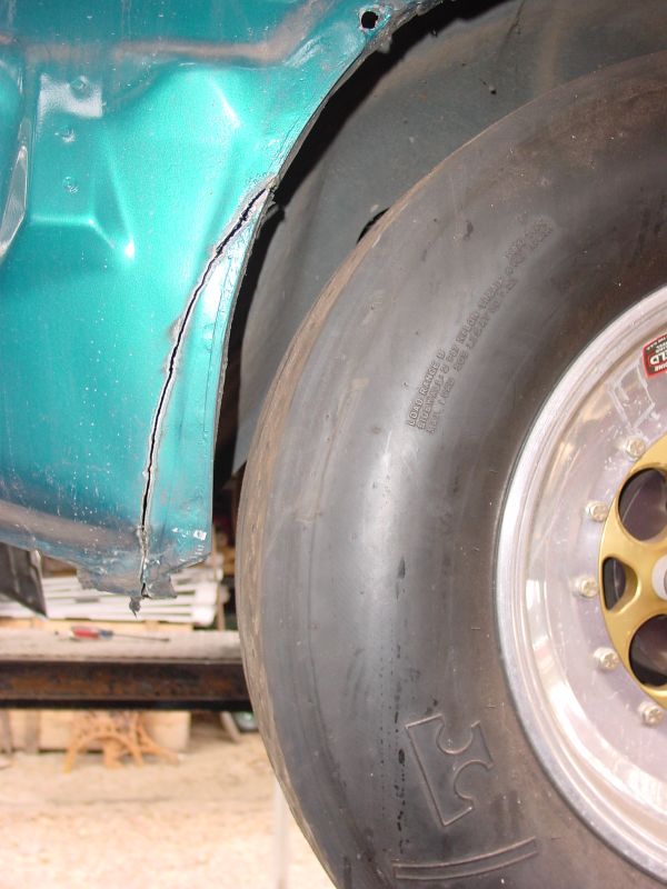
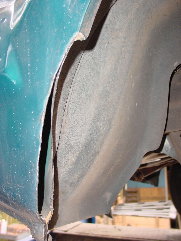
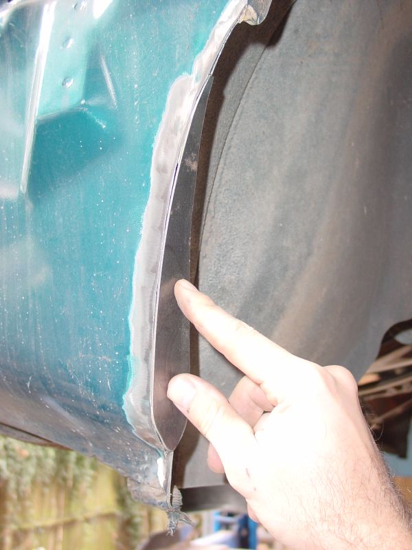
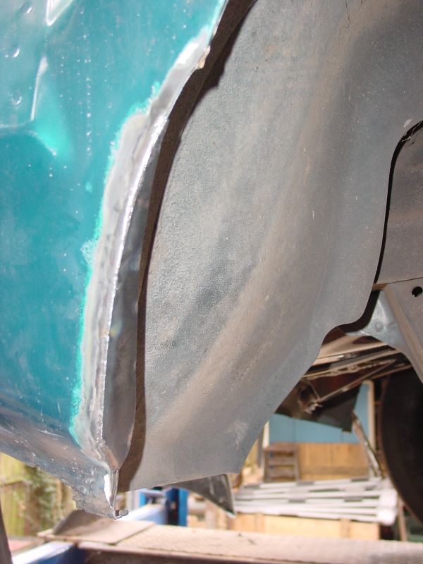
The factory rear wheelwells measure 30" at the widest point. Due to the irregular shape of the wheelwell, it is necessary to open it up to about 32" to accommodate a 30" tire. Although we now have only 28" x 12.50" tires on the car, I wanted to make sure we could run a 30" tire when it becomes necessary. This requires sectioning the plastic bumper cover and removing part of the lower quarter panel. The pictures shown have the modified bumper cover already completed and deal mainly with the quarter panel underneath. In the picture to the left, you can see how the bumper cover was reworked to provide a rounder wheel opening. |
 |
 |
 |
 |
|
In these images, you can see the steps that were taken
to clearance the quarter panels. Click any image for a larger view.
|
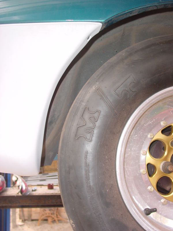 |
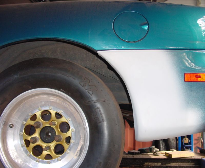
End Result
|
 |
April 2nd
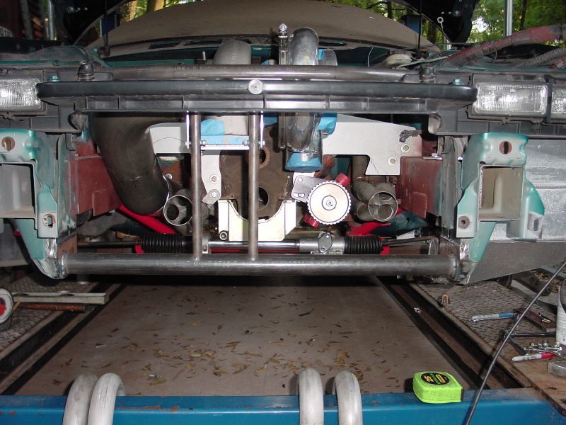
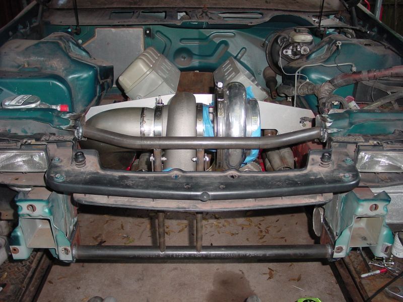
We finally were able to start on the headers and these next few images show the progress to date. Because of the extreme heat generated by turbochargers, we chose to use .065" wall 321 stainless steel to build the headers and y-pipe. While 321 stainless is not the cheapest stuff in the world, it will hold up the longest and look good doing it. Because of the high rpm this motor is capable of, we chose 1-7/8" primaries with a 3" collector and y-pipe. The downpipe is made from 5" 304 stainless steel that will be ceramic coated at a later time. If you have an F-Body, I don't need to explain how cramped this engine bay is. We had to use some creative thinking in order to plan the turbo and intercooler positioning, header and y-pipe routing, and intake plumbing, not to mention the twin Deltagate wastegates and Godzilla blowoff valve. We ended up finding room but it will definitely be cramped.
|
1 |
2 |
3 |
|
In order to make enough room for the turbo, it was necessary to fabricate a new radiator core support that provided more frontal room. The factory upper and lower braces were cut out, capped and then chrome moly tubing was welded into place(images 2 and 3). While weight savings was not really our goal in doing this, we ended up saving 7 lbs. The result provided 2.5" of additional turbo clearance, not to mention the fact that it strengthened up the front end and provided a more rigid mount for the turbo. Once all the intake plumbing is routed, two additional supporting tubes will be welded in to triangulate the shocktowers and core support. The turbo by itself weighs 46 lbs. and must be supported without placing weight on the headers. Since there is no physical mount on this turbo other than the exhaust flange, we had to make a double flange - one to support the turbo and one to seal the down pipe(image 1). Now that the turbo is in a fixed location, we can start routing the headers and y-pipe. In these images, the collectors have been positioned and we have started to route the primary header tubes. You can also see the beginnings of our 5" downpipe. |
April 15th
The next few images basically just show the continuing header progress. The headers/y-pipe/exhaust have been by far the most challenging part of this buildup. While finding room for the turbo and intercooler seemed tough enough because of their physical size, routing 1-7/8" primary headers forward along side a 5" downpipe on the passenger side has proven to test our capabilities. Despite the difficulty, we were successful and the results can be seen below.
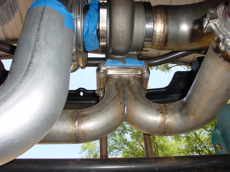 |
These two images show various angles of the turbo plumbing.
The fabricated inlet flange and 3" merge can be seen in the image
to the left and the whole setup is pictured in the right image.
|
 |
 |
 |
 |
|
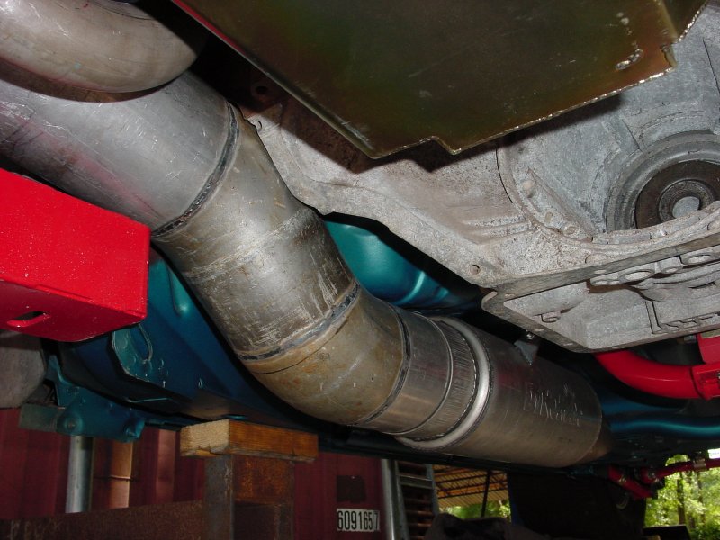
These few images show the down pipe and exhaust from various
view points. The down pipe was sectioned at various points and stainless
v-band clamps were used to seal the connection points. This was necessary
to allow the pipe to be removed in sections instead of requiring dropping
the k-member. The headers on the passenger side cannot be removed without
first removing the down pipe. As you can see, it is very tight in this
area. Once everything is complete, it will be necesarry to further clearance
a few areas to reduce rattles and provide additional space for movement.
Any image can be clicked for a larger view.
|
|
These images show the mounted 5" Dynomax muffler
that fit neatly into the stock catalytic converter recess. Even with a
6" muffler body, the lowest point is almost even with a deep transmission
pan. Although this is considered a race muffler because of it's straight
through design, turbo cars are relatively quiet to begin with and this
should tone it down for all but wide open throttle. Once everything is
clearanced, the entire down pipe and muffler will be ceramic coated.
|
 |
 |
Next few updates - Wastegate mounting, Intake tubing and blowoff valve mounting, '98 front end installation, Radiator mount fabrication, and more!.
GO TO PAGE 1 - 2 - 3 - 4 - 5 - 6 - 7 - 8 - 9