BMR 8 SECOND PROJECT CAR BUILD-UP
....The purpose of this page is to provide a monthly status report over the course of a year on the BMR project Camaro. This will be a detailed buildup of the entire process so that the viewer can follow along and see just what it takes to build a streetable 8 second F-body. Streetable? "Yeah, right" you say, "a race car with street tires and headlights is more likely". This is not the case with the BMR project car and if you follow along with the buildup you will see that the car will retain a full interior including power windows and seats, stock wheelwells(no tubs), and most important - a complete, off-the-shelf BMR suspension! That's right, this car will run 8's with the same suspension that is available to any BMR customer. This car is being built solely to explore the potential of our current product line and the joy of a 150 mph pass on streetcar suspension and 10" tires has nothing to do with it:)
THE CAR: The car being used for the buildup will be my ever faithful daily driver for the last 6 years, a 1994 Teal Z28 6 speed. This car has been a test mule for many products and has been taken apart more times than I can remember. The interior will remain stock except for gauges and an NHRA legal chrome moly rollcage. As of this writing, the car is still being driven while parts are accumulated.
THE ENGINE: This is the point where some people may lose interest while others will gain more interest. The engine being used for this buildup is a twin turbocharged SB2 small block Chevrolet that will produce somewhere around 1200-1300 horsepower. "How is that considered streetable?" you ask. 15 years ago, it wouldn't be possible, however with todays fuel management technology combined with turbocharging, a truly streetable combination can be achieved with the right combination of parts.
THE SUSPENSION: As stated earlier, this project car will run off-the-shelf BMR suspension products. All product installations will be fully documented in this article with picture updates regularly. Driveline consists of a Hughes Turbo 400, Mark Williams chrome moly 4" driveshaft and a Moser Ford 9" rearend. Rear suspension will consist of a BMR Xtreme duty chrome moly torque arm, chrome moly tubular control arms, chrome moly adjustable panhard rod, weld-in relocation brackets, boxed subframe connectors, and BMR dragrace anti-rollbar. BMR rear springs will be combined with Hal 12 way adjustable shocks. Front suspension will consist of a BMR tubular K-member, tubular upper and lower a-arms and Hal coil over adjustable shocks.
IN THE BEGINNING
| April 14th |
 |
The first thing we will address in this
buildup is the rear end since the factory 10 bolt has durability issues with
even stock motors. A Ford 9" was chosen for it's superior strength and
versatility. Moser and a few
other companies build a 9" Ford rearend with all the required brackets
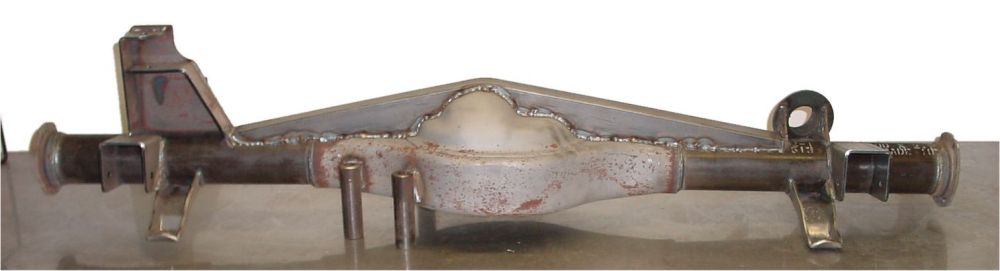
to make it an F-Body bolt-in.  It
comes with control arm and shock mounts, panhard rod mount, and a removeable
torque arm mount(see picture 1a). With the power this motor will generate
combined with the hefty 3600lb. weight, I felt it was necessary to go
It
comes with control arm and shock mounts, panhard rod mount, and a removeable
torque arm mount(see picture 1a). With the power this motor will generate
combined with the hefty 3600lb. weight, I felt it was necessary to go 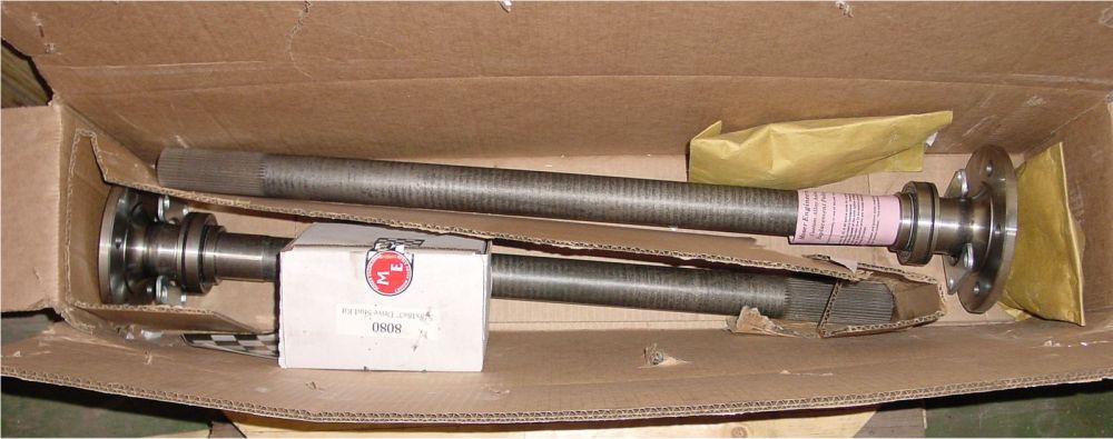 overkill
and chose 40 spline, gun drilled Moser alloy axles with 5/8" studs(picture
1b).
overkill
and chose 40 spline, gun drilled Moser alloy axles with 5/8" studs(picture
1b). 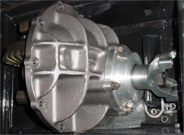 Also
a nodular center section(picture 1c) with billet front yoke was chosen to
eliminate any concern for parts breakage. The housing was ordered through
Moser with a pre-installed back brace and 4" narrower width to allow
a dished wheel. The first thing that was apparent after receiving the rear
end was, what I feel, inadequate welding on the housing. Below are some before
and after pictures of what was strengthened or rewelded. Additionally we installed
a set of weld-on control arm relocation brackets to allow instant center adjustments.
Also
a nodular center section(picture 1c) with billet front yoke was chosen to
eliminate any concern for parts breakage. The housing was ordered through
Moser with a pre-installed back brace and 4" narrower width to allow
a dished wheel. The first thing that was apparent after receiving the rear
end was, what I feel, inadequate welding on the housing. Below are some before
and after pictures of what was strengthened or rewelded. Additionally we installed
a set of weld-on control arm relocation brackets to allow instant center adjustments.
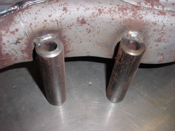 ... ...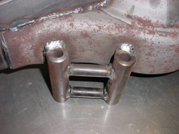 |
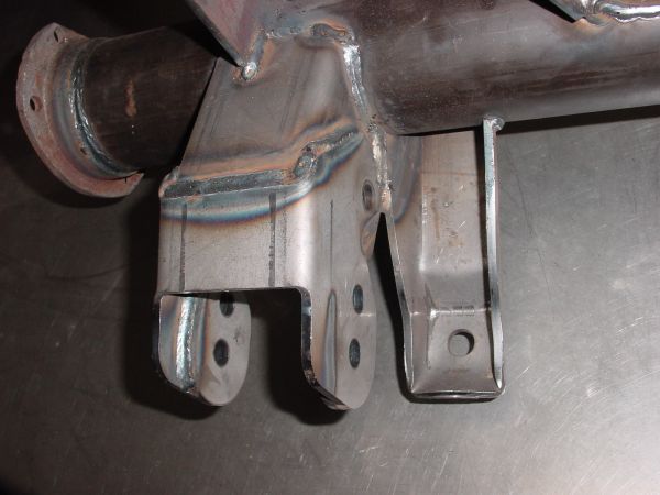
These are the mounts Moser welds to the housing for attaching the torque arm. The torque arm works basically like one big ladder bar. As the rear end tries to rotate upward under acceleration, the torque arm tries to lift the front of the car. This puts a lot of stress on the torque arm mount and I didn't feel the small welds from Moser were adequate for the amount of weight and horsepower this car will exhibit.. |
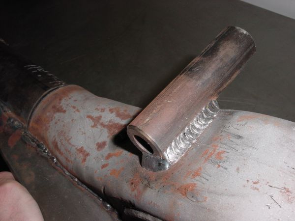
| More before and after images of the torque arm mounts illustrating the additional welding reinforcement. |
 ... ... |
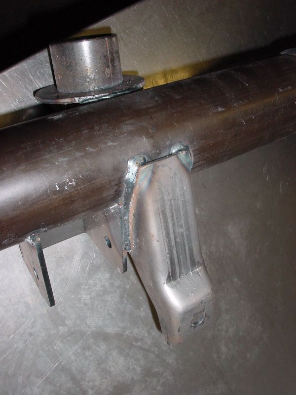 ... ... |
These images show the control arm and shock mount area. While it probably doesn't make much of a difference here, I finished up the welding on the shock mount and also welded the inside of the control arm mounting brackets. Additionally control arm relocation brackets were added to allow "instant center" adjustability. |
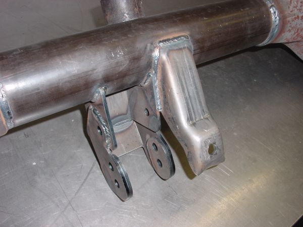
| In some extreme instances, housing deflection can present a problem in high horsepower applications. Gussets were added throughout the perimeter of the case to minimize deflection. I specifically placed two gussets inside where the torque arm mounts were welded to add some additional strength in this critical area. |
 |
 |
A backside image of the installed control arm relocation bracket. |
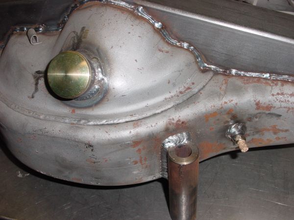
| Moser housings are shipped without any drain plugs or fill plugs so these were purchased from Mark Williams and installed as well as a new housing vent. |
 |
MAY 29th - This update is not actually a "progress" update since we are still accumulating parts and haven't actually started on the car itself yet. In the meantime, we thought we would at least show some of the items that will be used in the buildup to keep your interest picqued. A few changes have been made since the first update. We have decided to go to a single turbo due to packaging limitations in the cramped F-body engine bay. Although the single turbo itself is much larger than the smaller individual units of the twin turbo setup, the single turbo allows us to use much less intake and exhaust tubing, simplifying the installation and creating more room in the engine bay. One other area that has changed is our horsepower goal. After considering the cars weight and our limited tire size dictated by OE sized wheelwells, we decided to step up the horsepower a notch to insure that our ET goal of 8.60's is met. If everything works according to plan, we will be pushing in the neighborhood of 1500 horsepower at full boost. In a tube chassis car, this power level could easily run low 7's all day long but in a heavy street car with stock style suspension, it will still be a challenge to meet our goal.
|
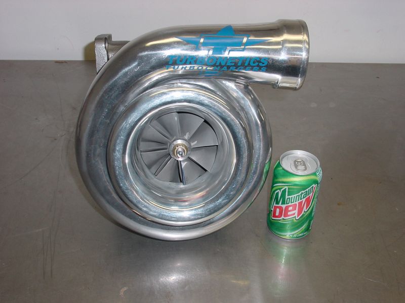
The turbo being used for this application will be the Turbonetics T-100. This turbo is actually rated to 1600 HP but I have seen dyno results on various cars that exceed this amount significantly. The photo to the right shows the turbo in comparison to a standard soda can to illustrate physical size. Click picture for a larger image |
 |
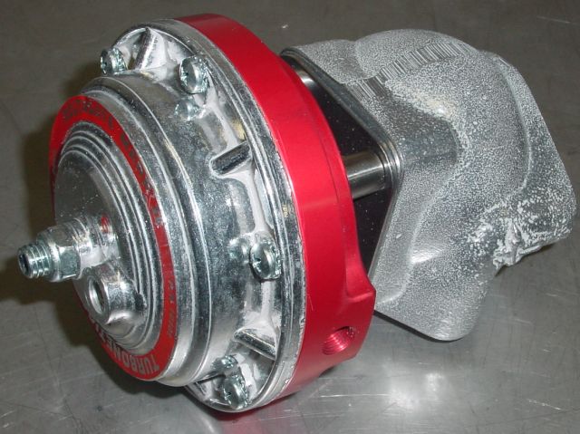 ........ ........ |
To the left are the Turbonetics wastegates and the Godzilla bypass valve. Two wastegates were required to maintain boost control and the bypass valve is used on the intake side to relieve pressure surges. Click picture for a larger image |
|
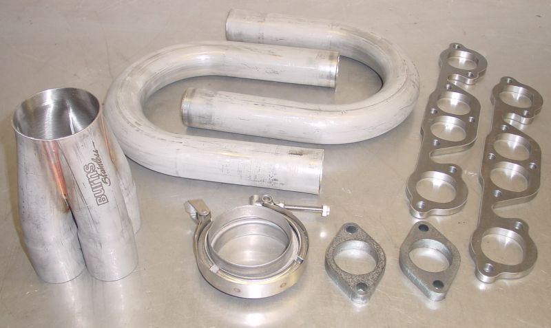
Turbocharged vehicles reach very high exhaust temperatures so if exhaust longevity is required, quality material must be used to withstand the heat. Since this is a custom application, we will be building the headers, y-pipe, and all the intake and intercooler tubing. All of the exhaust will be made from 321 stainless steel tubing and all intake tubing will be aluminum. To the right are some of the various parts that will be used to construct the headers. All tubing, collectors, and header flanges are from Burns Stainless and I must say very high quality. Click picture for a larger image |
 |
GO TO PAGE 1 - 2 - 3 - 4 - 5 - 6 - 7 - 8 - 9