January 2nd
In the next few updates, we will be focusing on locating key engine components. We have 3 large components that must be located before we can even start with the header fabrication - the dry sump tank, the turbocharger, and the intercooler. Once the proper layout is established, we can begin mocking up various header configurations to ensure the most optimum design for accessibility and future maintenance. This update will focus on the intercooler location and mounting.
|
|
|
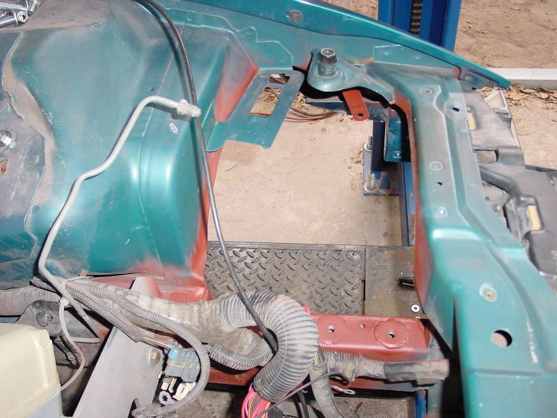
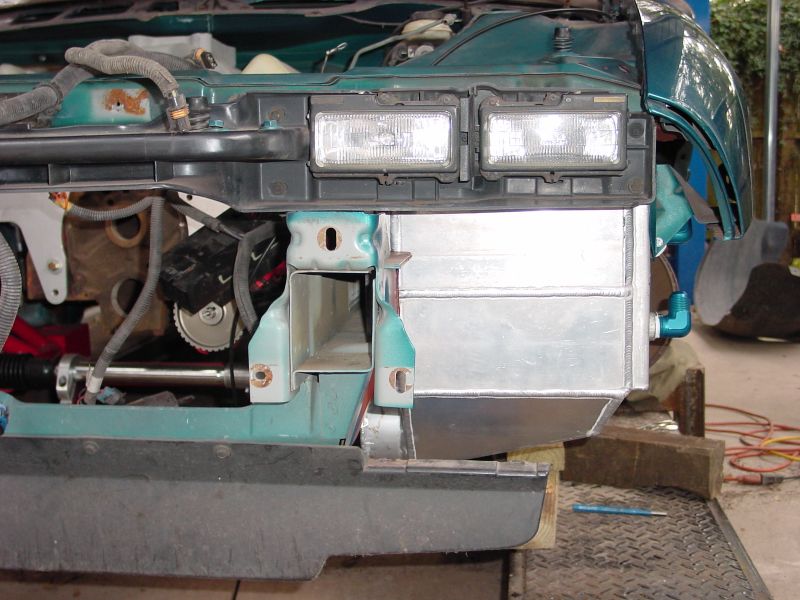
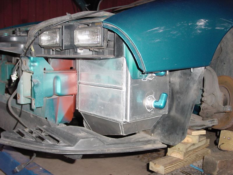
| In these two images, you can see where the drivers side front wheelwell was modified to accept the air-to-water intercooler. It was necesarry to remove and reinforce a section of the framerail as well as clearance an extensive portion of the core support in order to provide the required clearance. Once all final cutting was done, the area was metal etched and primed. Once the engine bay is finished, the entire assembly will be disassembled and the whole engine bay will be repainted the factory color. |
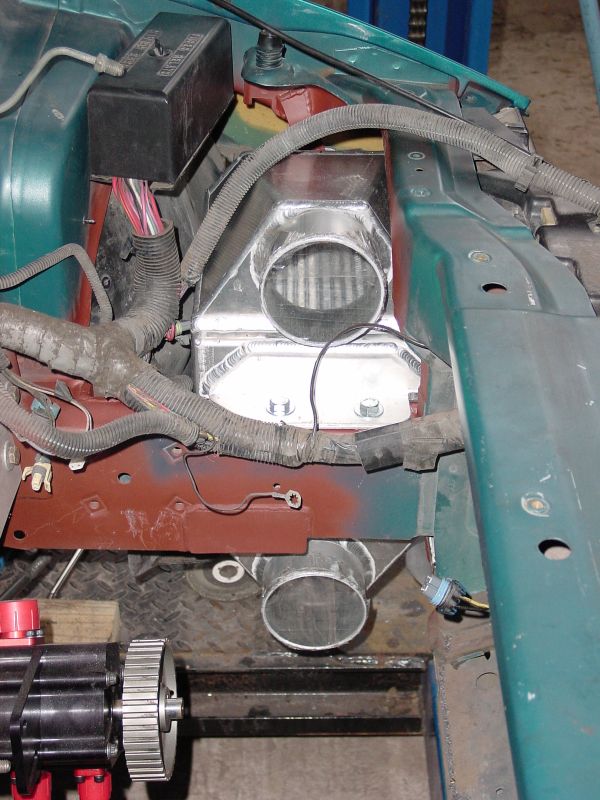 |
This image shows the installed intercooler from the point of view of the engine bay. The bottom tube is the inlet while the top tube will connect to the throttlebody with a 4" aluminum elbow. It still looks like there is plenty of room in the engine bay at this point but with the turbocharger, dry sump tank and lines, and all the exhaust and intake tubing that will be going in this space, it will definitely be a tight fit! |
|
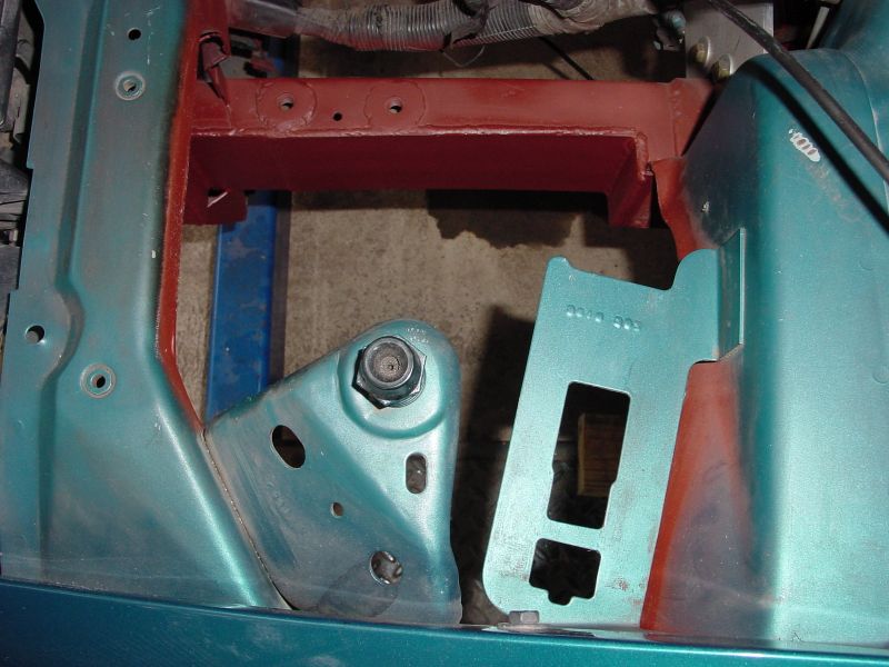
In these two images, you can see what a tight fit it
was "cramming" the intercooler into this spot. The intercooler
is butted right up against the back of the headlights and the fender's
inner mounting brace required a new mounting tab that is now attached
to the intercooler itself.
|
 |
 |
January 21st
This update just illustrates the intercooler plumbing and mounting of the dry sump tank.
|
1
|
2
|
3
|
 |
 |
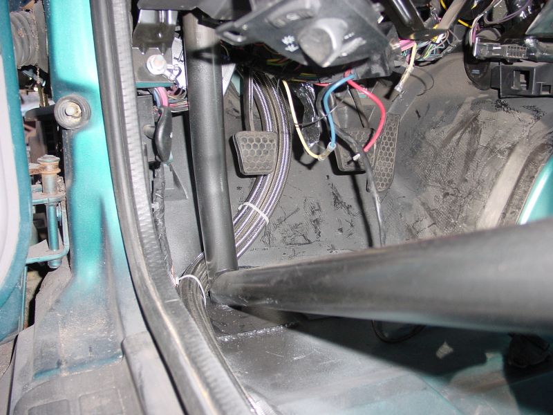 |
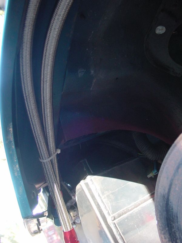
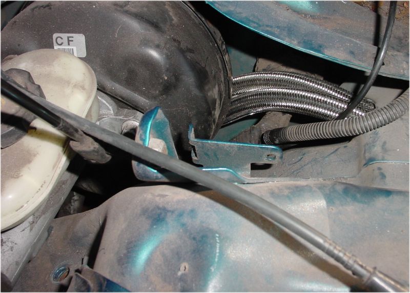
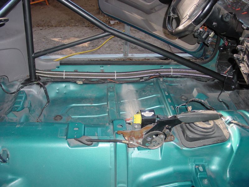
| Image 1 shows how the -12 water lines run up through the fender. Once the inner wheelwell is installed, these will be completely hidden. Image 2 shows where the lines come up through the fender, behind the booster, and through the firewall. Once the slave cylinder was removed, the lines were routed through this existing hole. Image 3 shows the lines running down the firewall behind the "now-useless" clutch pedal. |
|
4
|
5
|
6
|
 |
 |
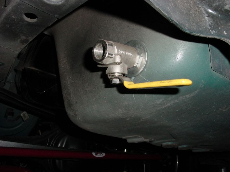 |
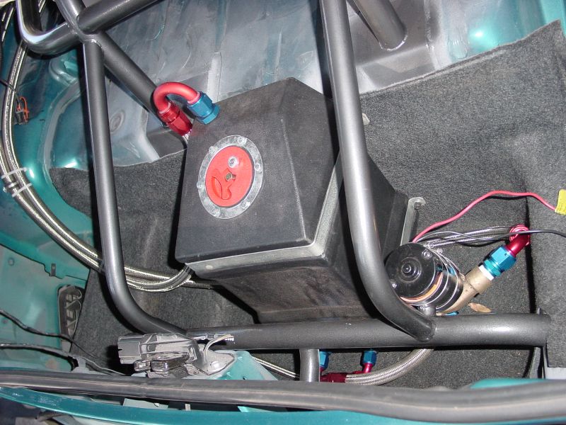
| Image 4 shows the -12 water lines routed next to the rocker panels. These will easily be covered by the new carpet once installed. Image 5 shows the plumbed water tank and pump. The pump receives freshly cooled water from the tank and sends it to the intercooler then the water is returned back to the top of the tank. There is also a -10 drain line that runs from the bottom of the tank to a bulkhead fitting and exiting underneath. This uses a standard stainless ball valve(Image 6). |
|
1
|
2
|
3
|
 |
 |
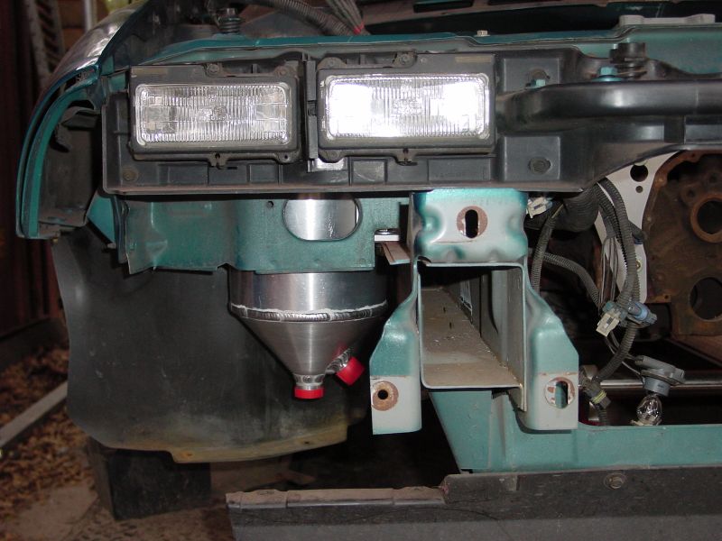 |
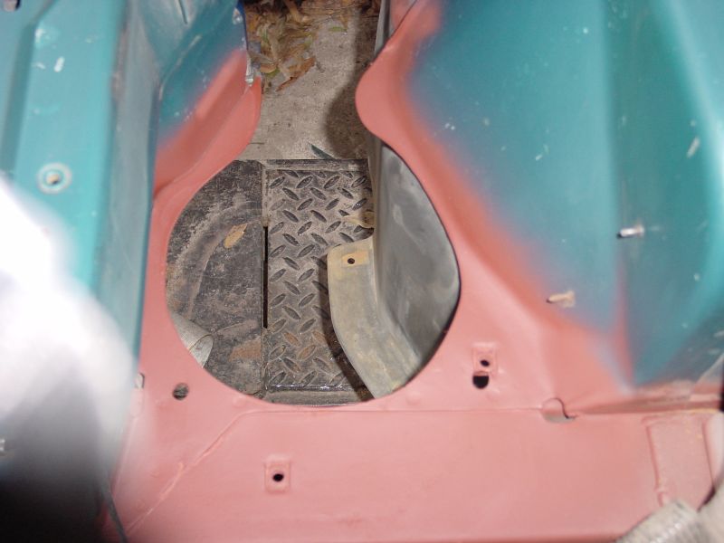
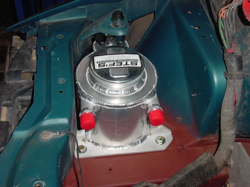
Image 1 shows what clearancing was necesarry in order to mount the drysump tank in what used to be the passenger side battery well. Once the tank was test fit into the hole, a bracket was fabricated and welded to the Stef's tank. The bottom oil heater and drain valve are easily accessible from underneath. Image 2 and 3 shows the front and side views of the mounted tank, click the images for a larger picture.
GO TO PAGE 1 - 2 - 3 - 4 - 5 - 6 - 7 - 8 - 9