September 19th
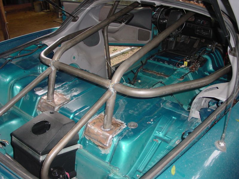
| Below you can see the subframe connectors, crossbrace and the beginnings of the torque arm install. Normally for an application with this much power, we would recommend boxed subframe connectors but in this case we chose to use the tubular version of the subframe connectors so that we could tie them into the rocker panel pinch welds for added strength. The tubular subframe connectors fit higher in the rocker tunnels allowing us to position our torque arm crossbrace higher in the chassis. This necessitated a little tunnel persuasion in order to provide the required clearance for the torque arm, especially since we intend to run a 4" driveshaft. Most cars with this level of power are tube framed and use a 4 link style suspension tied directly into the rollcage. Since we are using a full bodied street car and off-the-shelf suspension and chassis parts, a few extra reinforcements were necesarry to increase the strength of the suspension mounting points. The drivers side floorpan was slit and the crossbrace recessed and welded into it and we are exploring the possibility of running two main bars down from the rollcage to further strengthen the torque arm pickup point on the crossbrace. Click on any picture below for a larger image. |
|
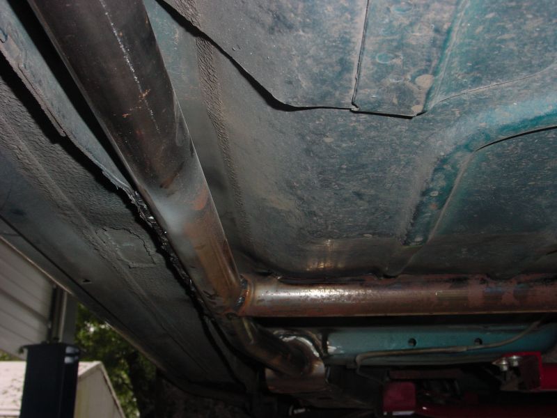
In a unibody car, the rocker panels are the main structural "bridge" that ties the front and rear subframes together. This picture shows how the rocker panel pinch weld was bent over and welded directly to the side of the subframe connector. This not only provides more rigidity by tying more points of the car together but also helps strengthen the crossbrace to minimize flex during hard launches. You can also see in this picture where the crossbrace was recessed into the floorpan for additional strength. |
|
Another image showing the recessed crossbrace. You can also see the Xtreme duty torque arm and dummy driveshaft being mocked up for clearancing the tunnel before painting. |
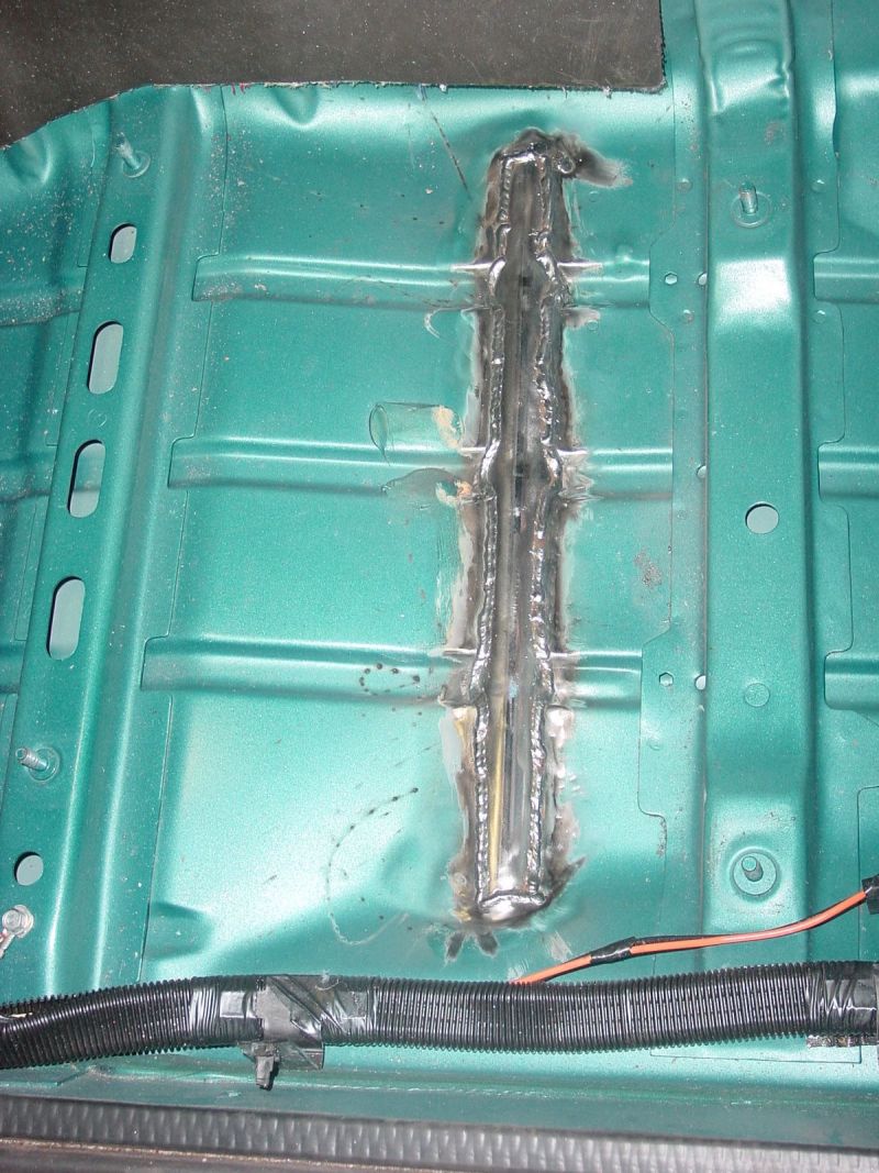
This is a picture of the crossbrace from the interior of the car. To illustrate where this is in relation to the interior, the four mounting studs shown on the two vertical floorpan reinforcements are the drivers side seat mounts. Once the floorpan is painted and the carpet and seats installed, it will be completely hidden. |
 |
October 8th
We have started working on the rollcage and this update shows to date what has been done so far. The cage is being custom built from 1-5/8" x .083" chrome moly tubing to keep weight down, the below pictures shows the cage from the main hoop back. Click images for larger views.
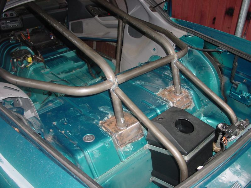 |
NHRA requires 6" x 6" mounting plates unless
the tubing is welded directly to a "traditional" frame rail.
This distributes the load over a greater area. Since the F-body chassis
doesn't really have any true frame rails(only formed sheetmetal), we made
custom mounting plates for each connection point and formed them to the
contours of the floorpan. Here you can also see where we are mocking up
a small fuel cell to be used as our water tank for the intercooler. A
large electric pump is mounted next to the tank and will circulate ice
water between the tank and intercooler.
|
 |
 |
 |
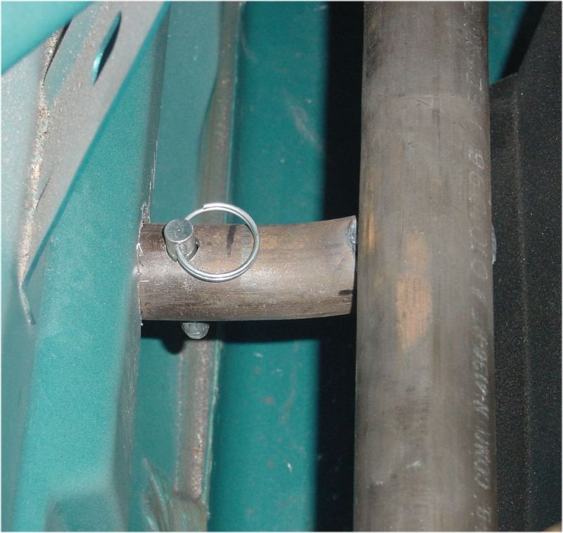 |
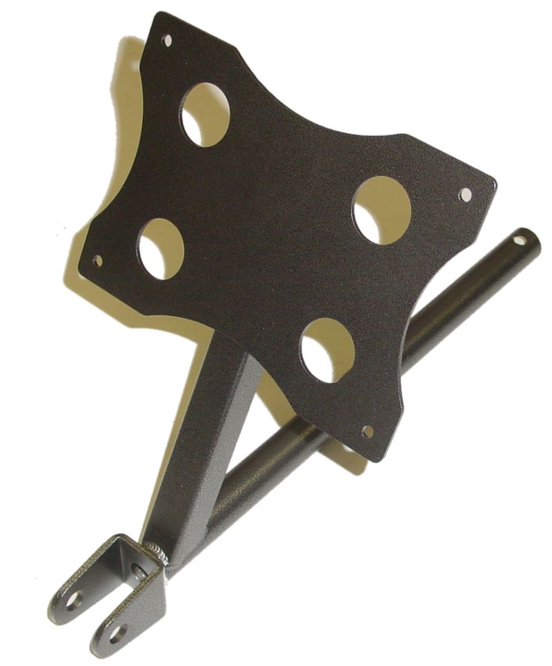
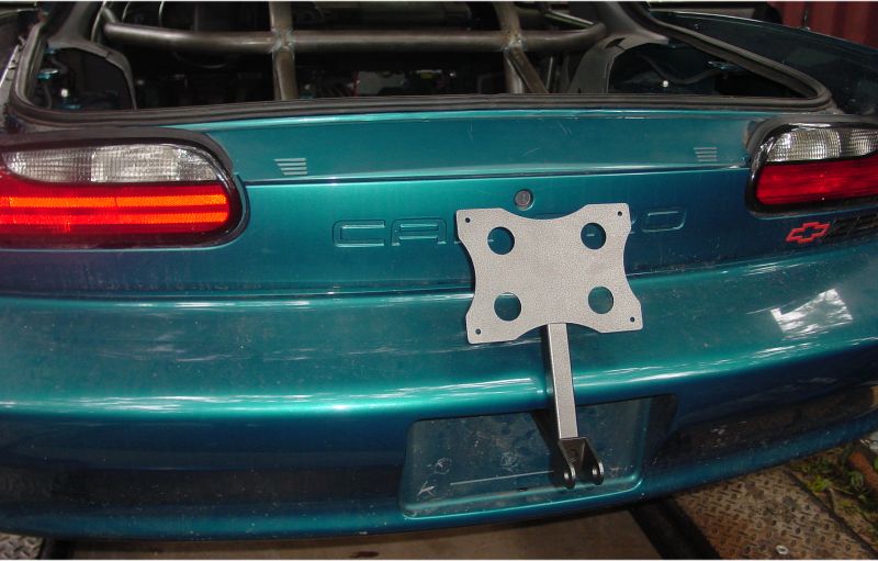
| These images show our fabricated parachute mount required for cars having the capability to exceed 150 mph in the quarter mile. The top section is what the chute itself mounts to while the bottom bracket is where the chute tether attaches. It is not visible in these photos but there is a section of tubing that ties the rear frame rails together just behind the water tank in the above photos. This is what both the two down bars from the cage tie into and also the chute mount. The chute mount was designed so that a quick pin can be pulled to remove the whole chute and mount assembly when the car sees street duty. |
October 17th
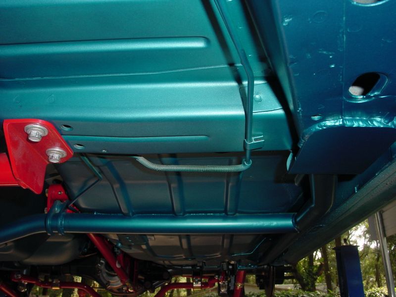
While we finish up the rollcage, I thought it would be a good idea to show the suspension once it was fully installed. Once all the welding was complete, we sanded and painted the bottom of the car with bare metal etching primer and then topcoated with the factory color. While it makes it difficult to see them in the photos, the subframe connectors and torque arm crossbrace were painted the OE color to blend in with the body.
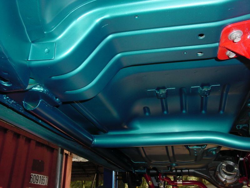 |
These images show the weld points of the subframe connectors
and torque arm crossbrace.
|
 |
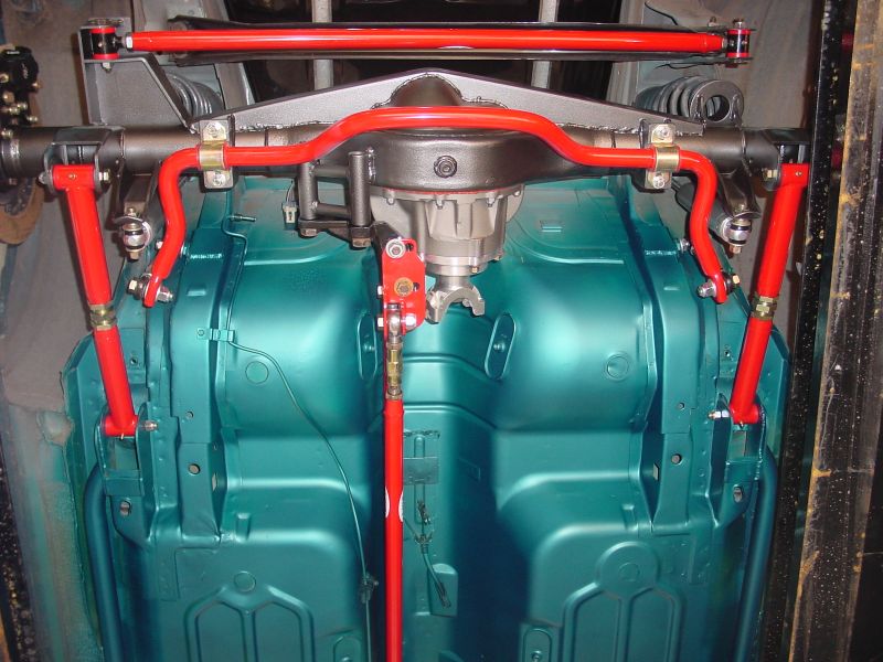 |
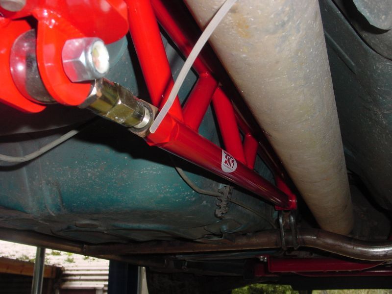
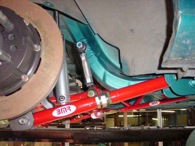
Here you can see the completed BMR rear suspension setup. The drag race style adjustable swaybar is a prototype as well as the Xtreme duty chrome moly adjustable control arms. Both of these items will become available within the next few weeks of this update. The swaybar is made from massive 1.25" 4140 cold rolled steel and has chrome moly, 5/8" rod ends with double adjusters. This bar is streetable yet allows the proper tuning for extreme applications such as this. Also visible in the picture is a chrome moly adjustable panhard rod, weld-in relocation brackets, and Xtreme duty chrome moly torque arm. |
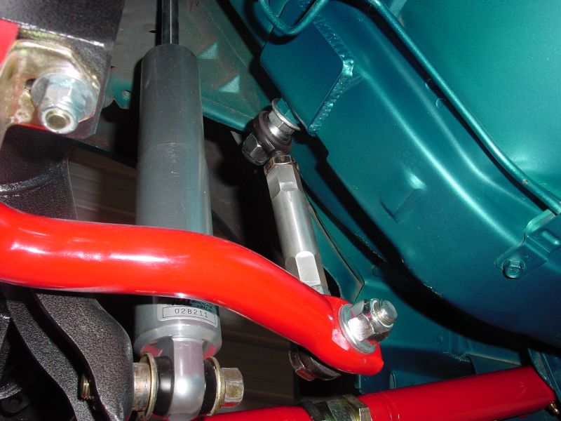
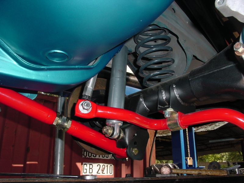
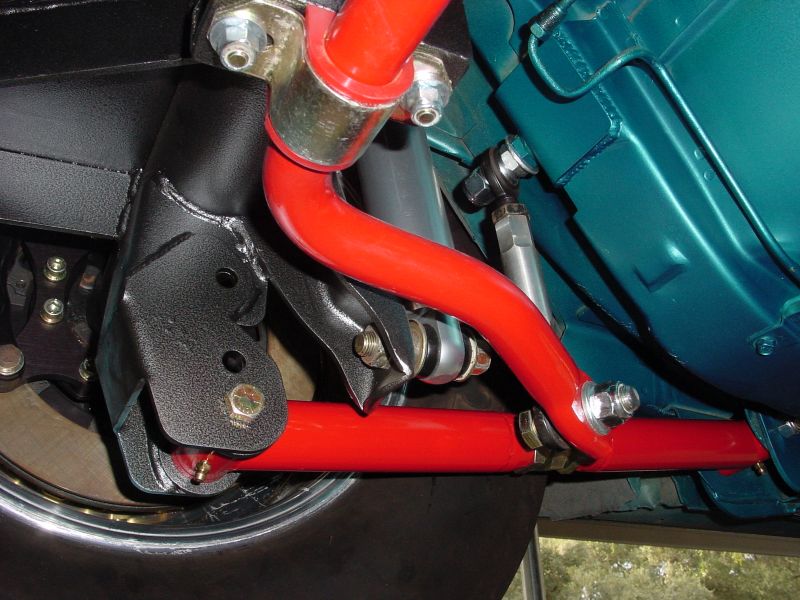
These next few pictures show closeups of the sway bar to illustrate mounting locations. The swaybar is provided with weld-in frame and body mounts as well as a set of Prothane bushings. Also visible in the pictures are the new Xtreme Duty chrome moly adjustable control arms.
 |
 |
 |
 |
GO TO PAGE 1 - 2 - 3 - 4 - 5 - 6 - 7 - 8 - 9