BMR 7 Second Mustang Buildup
PAGE 6
July 27th, 2005
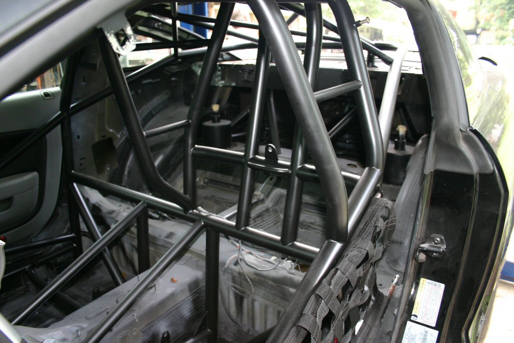
There has been a lot of time consuming finish work done on the car within the last few months. Most of it is not worth following in the buildup but will have completed images posted as the car starts coming together. We finished all the sheetmetal work and sealed up all the rollbar pass-through holes in the floorpan, made fuel tank and intercooler tank mounts, battery mounts, window net mounts, parachute cable mounts, seat belt mounts, and a lot of other little things that I can't even think of at the moment. Basically everything that had to be done in order to get paint on the rollcage was done. In this update, you can see the finished product before the interior goes back in the car.
 |
 |
 |
October 17th, 2005
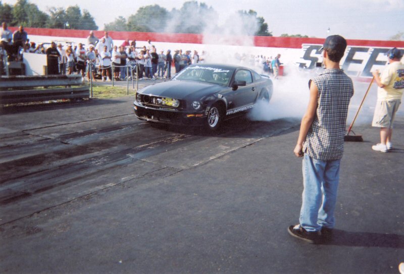
As you can tell, it's been difficult to keep these pages updated; our extra time lately has been consumed by the car. The car has actually been finished even though the webpage doesn't show progress. We just got back from the Orlando World Street Finals where the car actually competed in the event running it's first and only pass of 8.65@167.8mph. We lost the torque converter on that pass and even though we thrashed to get it fixed, it just didn't happen. All in all we were thrilled with the time and it made the past three weeks of thrashing worthwhile. The potential of the car can be realized when you consider that the pass was made rolling off the starting line at about 70% power. In Outlaw trim with a 100mm turbo, the car chassis dyno'd over 1300hp to the rear wheels. The dyno software is only calibrated to display up to 1300hp yet the curve continued to climb to an estimated 1400-1500hp.
The images below show the progress over the past 3 months. I will post images of the finished car along with some track video later this month.
 |
 |
 |
|
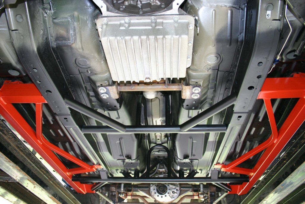
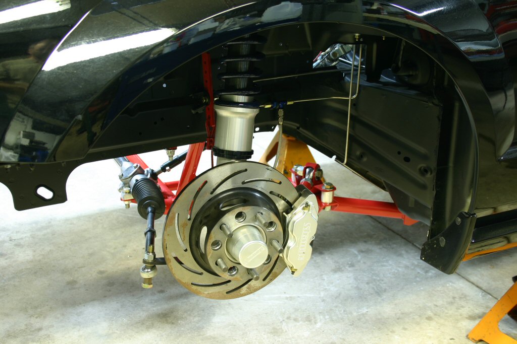
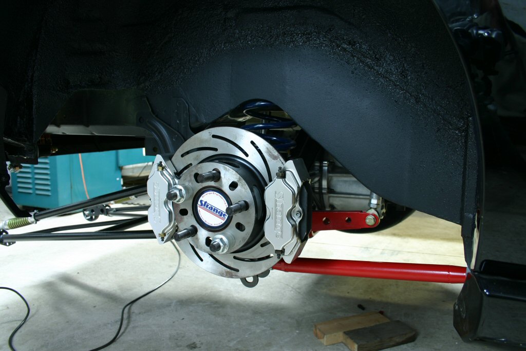
In these images you can see the entire Strange brake setup installed on the car. This setup worked so well, we never even had to pull the parachute cable. You will probably notice that we decided to run dual calipers on the rear. At the last minute before heading to the track, we realized that our Weld beadlock wheels interfered with the calipers requiring them to be removed and machined for clearance. Also shown in the images above is our tubular K-member installed with a manual rack and pinion. We machined an inner tie rod adapter that threads onto the main rack bar, extending the width of the inner tie rod pivot points 4". This places the inner tie rods inline with the A-arm pivot points, minimizing bump steer. We will have these K-members and modified rack and pinions available to the public shortly. |
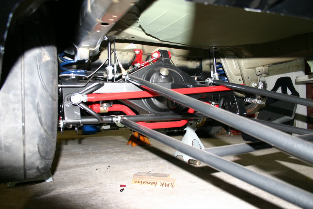
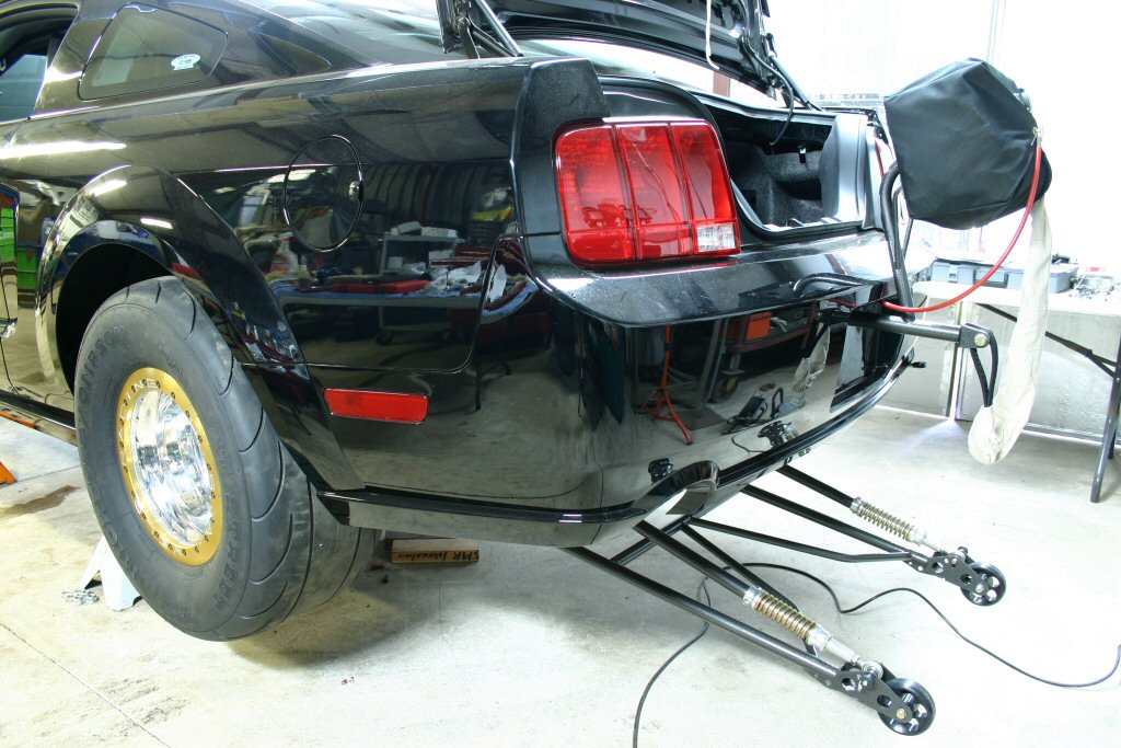
| Completed rear suspension and wheelie bar images. |
 |
 |
 |
 |
 |
 |
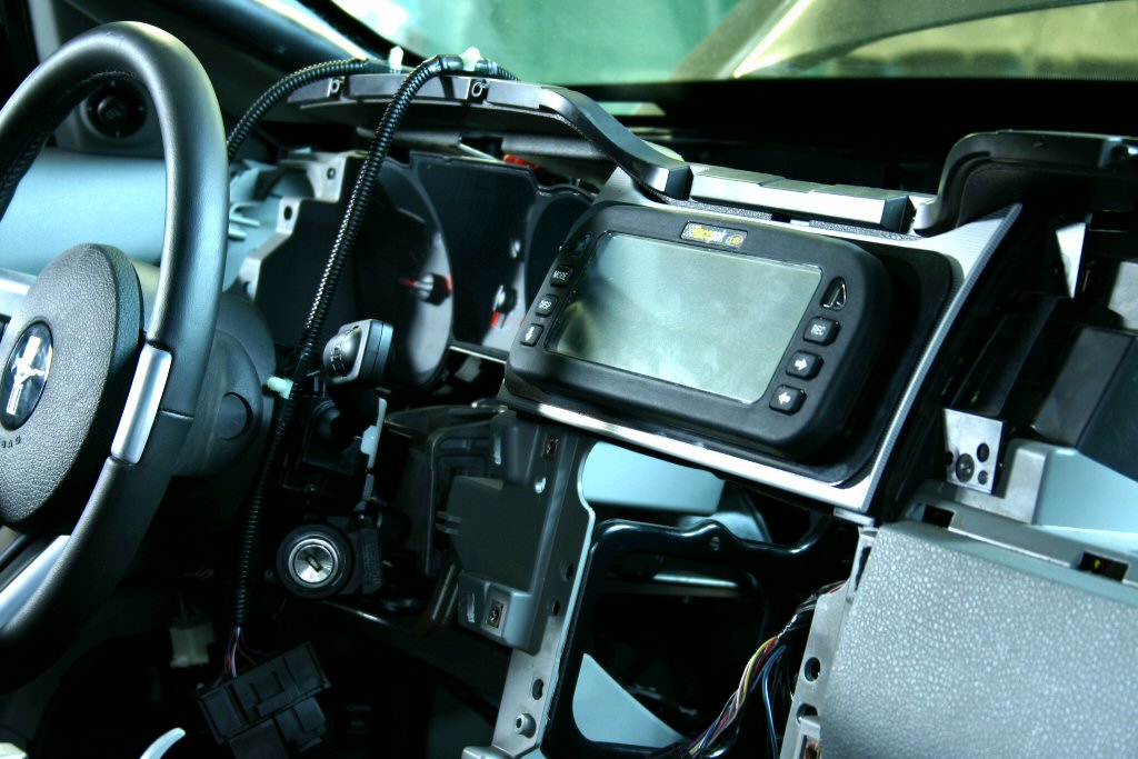
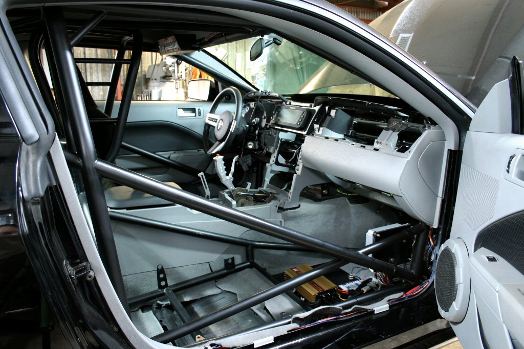
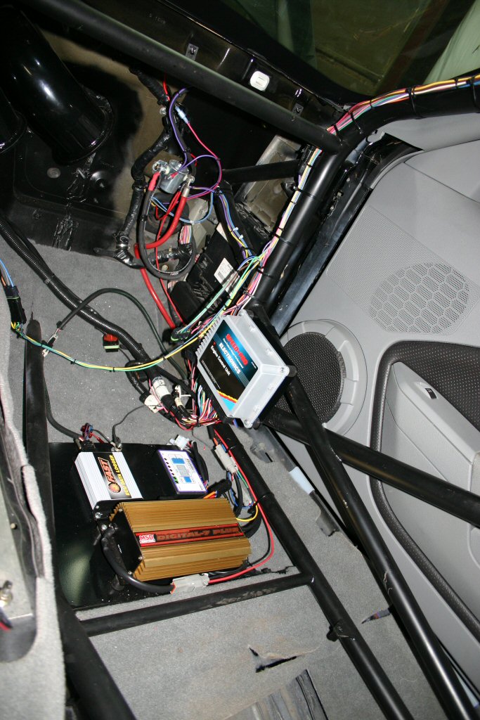
| In the above images you can see some of the interior photos of the car along the process. We mounted the RacePak gauge cluster where the center AC vents used to be. In the second image you may notice that the emergency brake is now the parachute handle. In the third image, the MSD Digital 7 Plus, FAST unit, and Innovative boost controller can be seen being wired. Additionally a RacePack datalogger was mounted on the same panel. The main switch panel can be seen in the 4th image. |
 |
 |
 |
 |
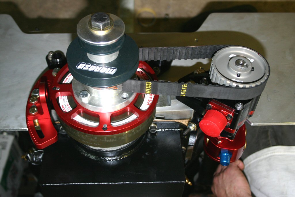
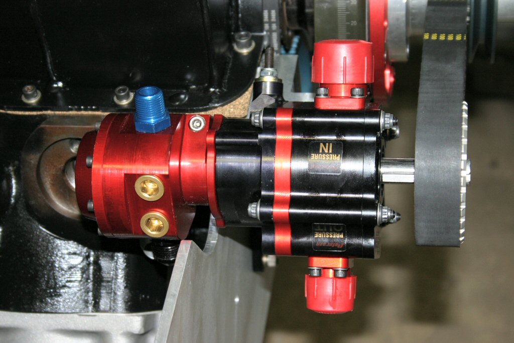
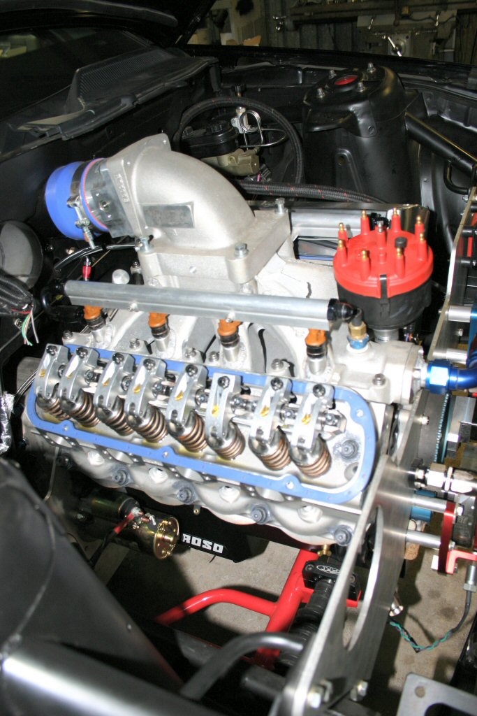
| In these few images you can see the motor going in the car for the final time. We are using a Peterson external oil pump that has a rear driven Waterman fuel pump. It makes for a very compact unit that tucks up tight to the block. This fuel pump is capable of supporting 2500 horsepower. Also shown in the last photo is the Moroso vacuum pump. |
 |
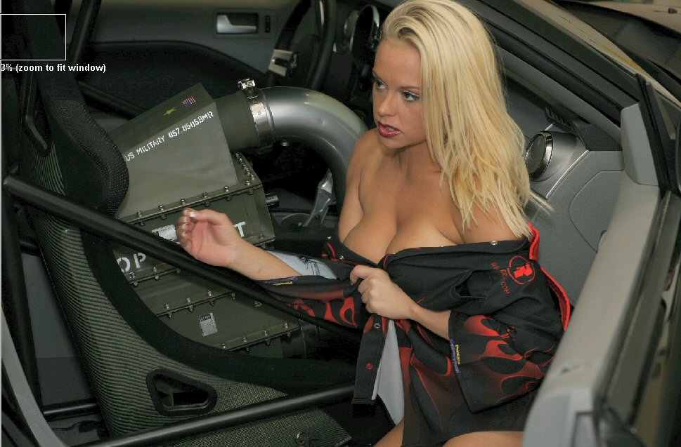 |
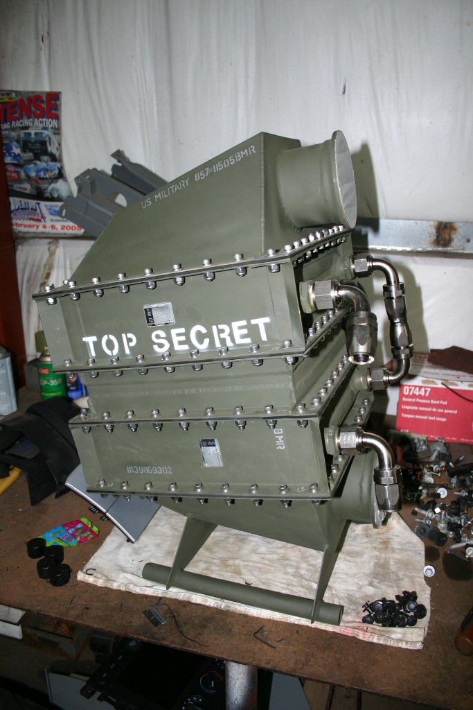
These are image of our custom intercooler. Since the cores came from a military helicopter, we thought it would be cool to make it look that way. The second image is from a photoshoot we had recently to update our catalog, brochures and downloadable wallpapers. |
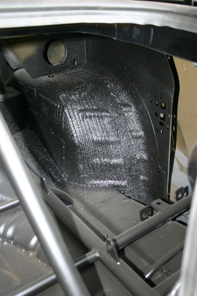
| This is the trunk area semi-completed. The drivers side tank is the fuel cell and the passenger side tank is the ice water tank for the intercooler. The intercooler tank also has a transmission cooler built into it that is submerged in the ice water. | 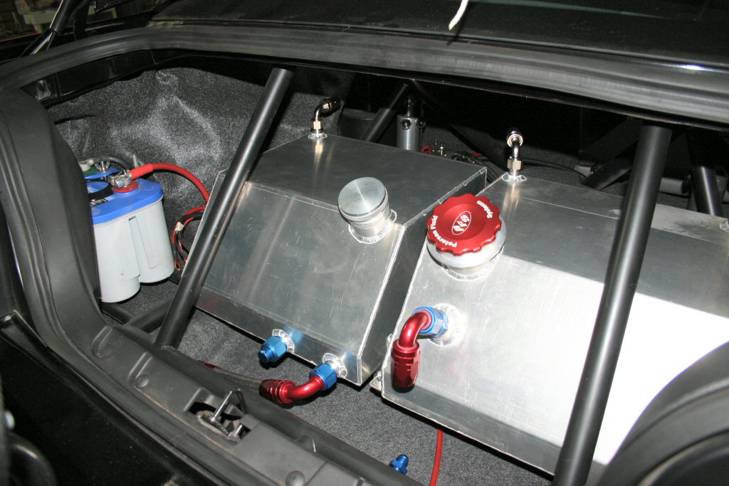 |
 |
 |
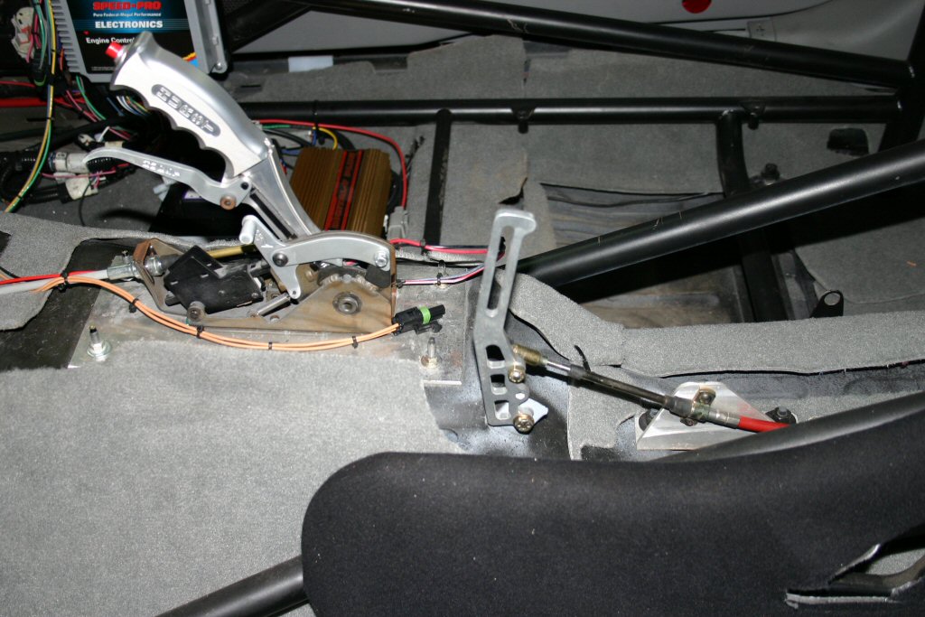
The emergency brake lever was removed and the parachute lever was installed in it's position. The second image shows the packed parachute mounted and ready to go. |
|
Just a few more images of the motor in the car while we were mounting accessories, making hoses, adjusting valves, etc. |
 |
 |
More images coming soon!
|
CLICK TIMESLIP FOR LARGER IMAGE |
 |
