BMR 7 Second Mustang Buildup
PAGE 4
Page 1-2-3-4-5-6-7-8-9
February 24th, 2005 - MOTOR
|
|
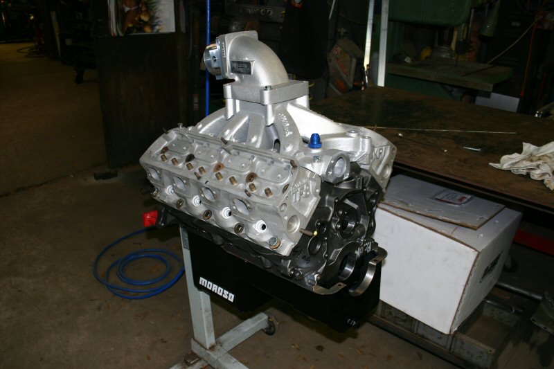
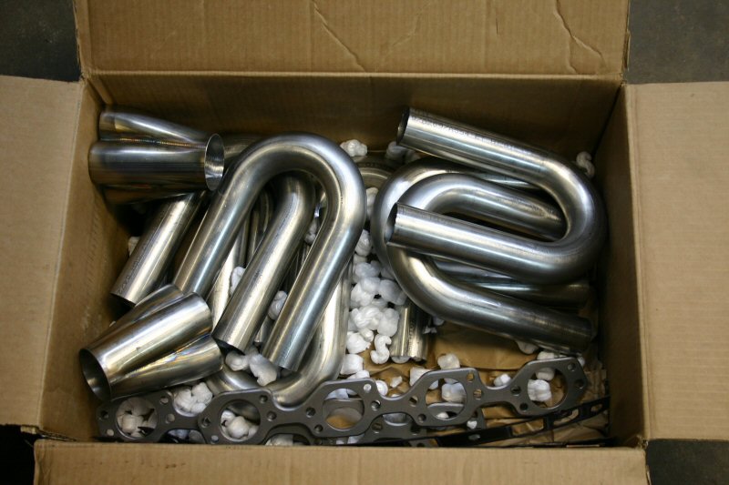
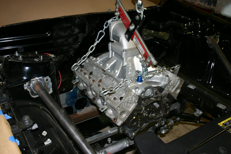
With the rearend waiting on axles, we assembled a dummy
motor to begin making motor mounts and headers. We ordered merged collectors
and a bunch of 1.75" stainless u-bends from Burns
Stainless. |
|
| This image shows the motor being positioned for midplate
and motor plate fabrication. The midplate is a combination mount and Powerglide
conversion. There are a few already on the market but none were wide enough
to fit this frame rail so we fabricated our own. To position the motor
side to side, the camshaft is centered with the pinion and then it is
positioned as high as possible to promote optimal weight transfer. Once
the mounts are finished, the next step will be header fabrication. |
|
March 1st, 2005 -
 ........ ........ |
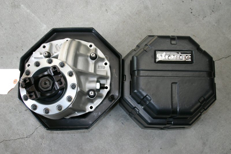
In the meantime, all of our Strange axle components arrived
so we could finish welding up the rearend. We chose the Strange Ultra
case which has a much larger pinion support, through bolts on the carrier
and a larger 9.5" diameter ring gear. Inside is a billet spool and
a 3:50 Pro gear. |
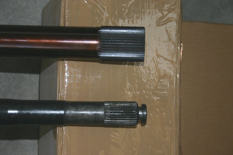
| We also chose to use Strange 40 spline gun drilled axles.
A typical hardening process can only temper the metal to a depth of around
1/4". When you gun drill an axle, it allows the axle to be tempered
on the inside and outside which makes it stronger even though there is
less material. A gun drilled 40 spline axle is actually lighter than a
35 spline solid axle. In this comparison, you can see the size difference
between an OE axle and the 40 spline axle from Strange. |
|
|
|
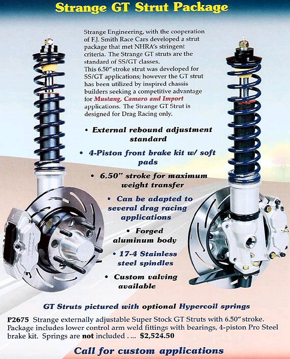
Arriving with our rear end components was the Strange GT
strut package. Since nobody is making a drag strut for this application
yet, we decided give this a shot. This is a lightweight, adjustable strut
and brake kit designed for drag race use in applications requiring a tall
strut. It requires a custom A-arm and upper mount. After speaking with
Strange, we thought we would be able to make them work in our application.
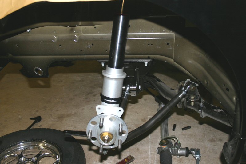
The rulebook says that any aftermarket strut and A-arm can be used as
long as it mounts to factory locations. We made a bolt-in adapter for
the upper mount that bolts to the OE strut tower in place of the rubber
factory mount. We also fabricated a custom chromoly A-arm for the bottom
that attaches to original mounting locations on the K-member. The picture
to the right shows the rough kit mocked up for measurements. With this
setup we replaced the factory strut, springs, upper strut mount, A-arm,
hub, brake rotor and caliper and dropped 80 lbs. off the front end! |
|
March 11th, 2005
| With the suspension done and the car sitting back at ride height the
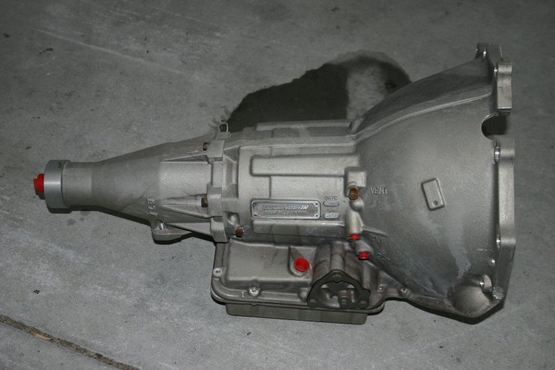
motor plates were made. In the meantime, our PTC
transmission and torque converter showed up so we were able to make our
transmission crossmember at the same time. This transmission has the best
of everything from the Kevlar clutches to the Dedenbear
case. |
|
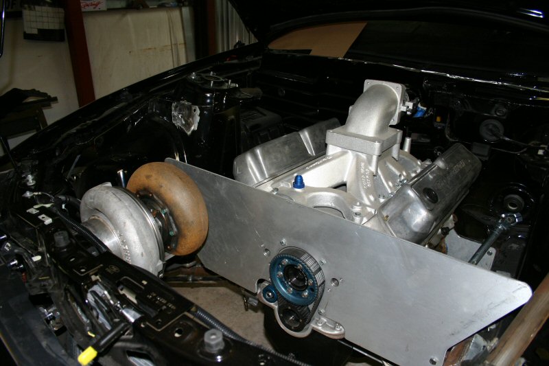
| The very first thing that must be done when building headers is to decide
where the turbo will be positioned. The turbo position dictates where
every other exhaust and intake tube in the engine bay will run so you
have to have all your components at the beginning to map the layout. Before
we could decide on a turbo location, we had to have the radiator in the
car so we made mounts to install a Griffin radiator as far into the nose
as possible. With the radiator mounted, we ended up mounting the turbo
directly in the center of the engine bay. This was necessary to allow
plenty of room for the 5" downpipe to make the 90 degree transition
out of the turbo. The headers and y-pipe will run low to allow room for
the downpipe next to the block on the passenger side. |
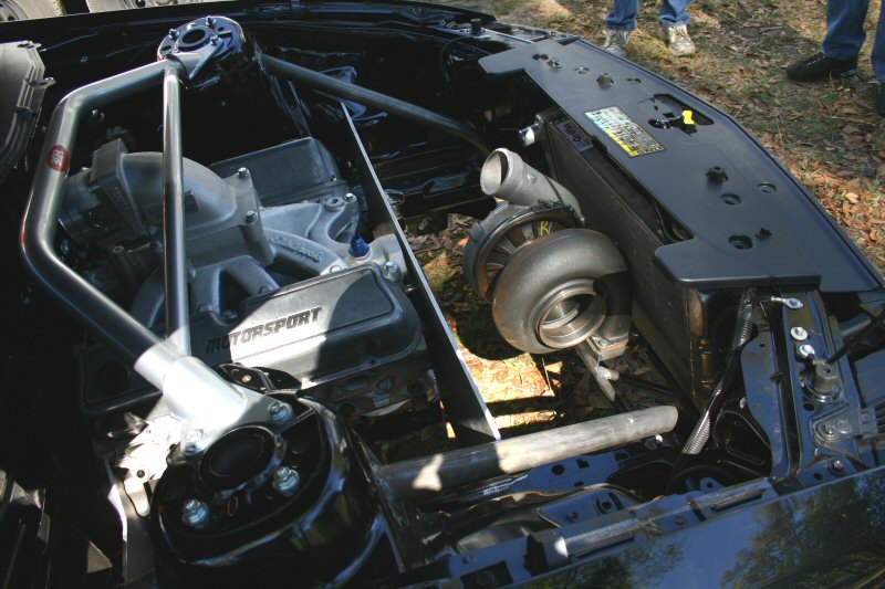
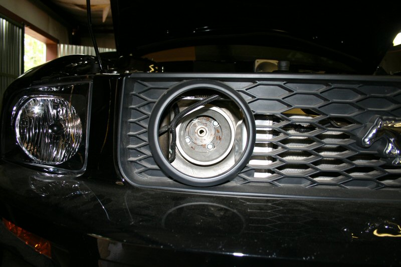
March 27th, 2005
Just when things seemed to be moving along, we decided to relocate
the turbo. When we started to mock up the headers and y-pipe routing, it was
determined that the turbo could be rotated 90 degrees and placed over towards
the passenger side. This will keep most of the turbo plumbing on one side
of the car and "tidy" up the engine bay. We integrated the turbo
mount into the frame rail and lined up the inlet of the turbo with the driving
light located in the grille opening. A duct will be fabricated later to channel
air directly into the turbo (depending on class rules).
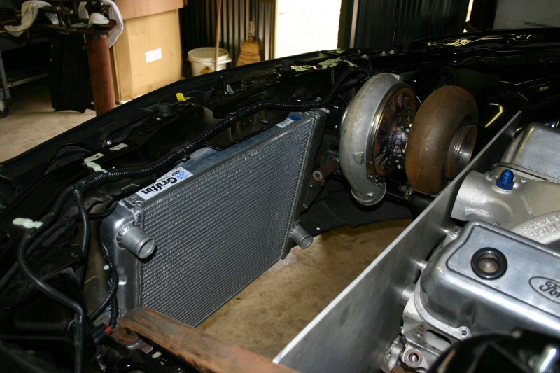
Once the turbo was repositioned, we had to relocate the radiator.
Fortunately, there was just enough room to get both the radiator and the turbo
inlet betwen the frame rails. Now we can begin fabricating the headers, downpipe
and inlet tubing.
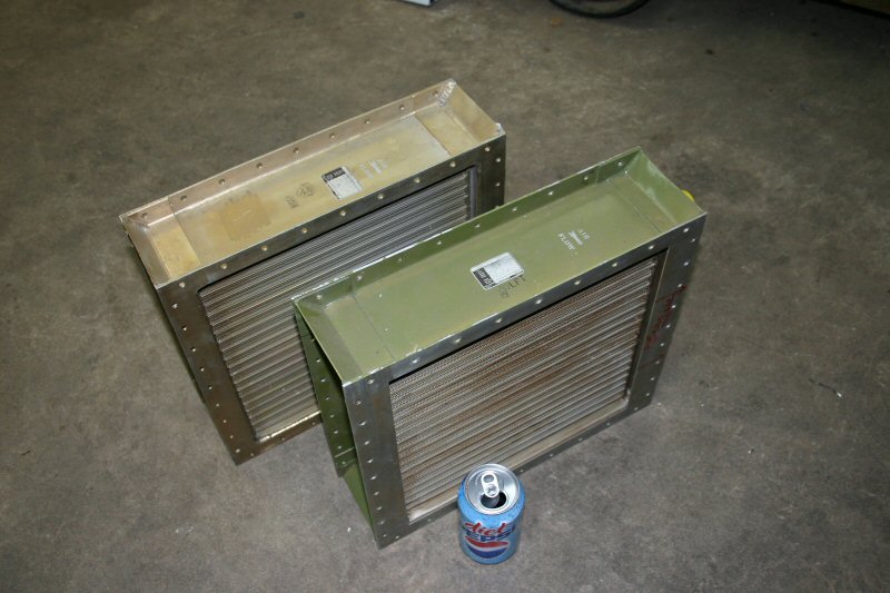
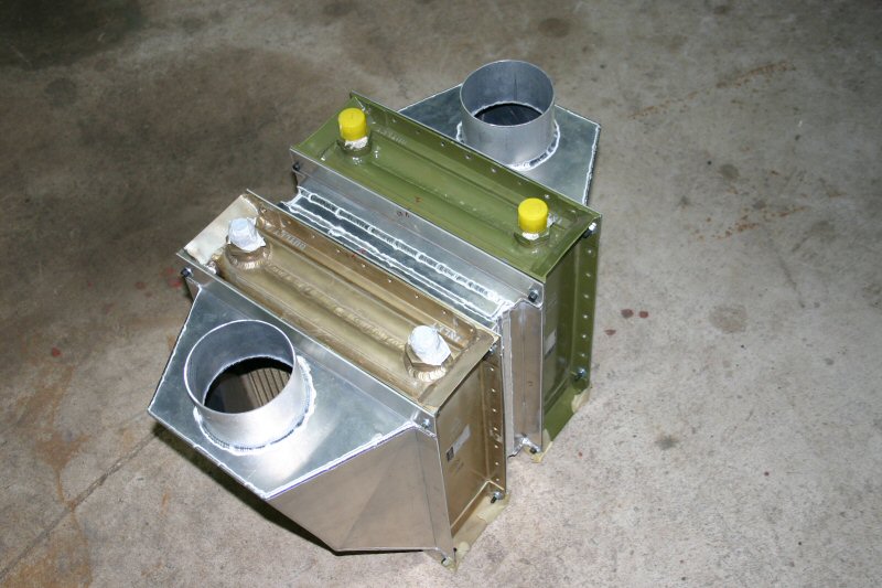
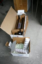
Before anything got started, we wanted to make sure that the
intercooler was positioned properly so we could map out our intake path. Instead
of buying a premade intercooler, we are building one using two highly efficient
cores from a military helicopter. These are actually oil coolers and were
chosen for there modular convenience and efficiency. The intercooler will
be positioned in the front passenger seat.
Page 1-2-3-4-5-6-7-8-9
 ........