BMR 7 Second Mustang Buildup
PAGE 5
March 31st, 2005
 |
 |
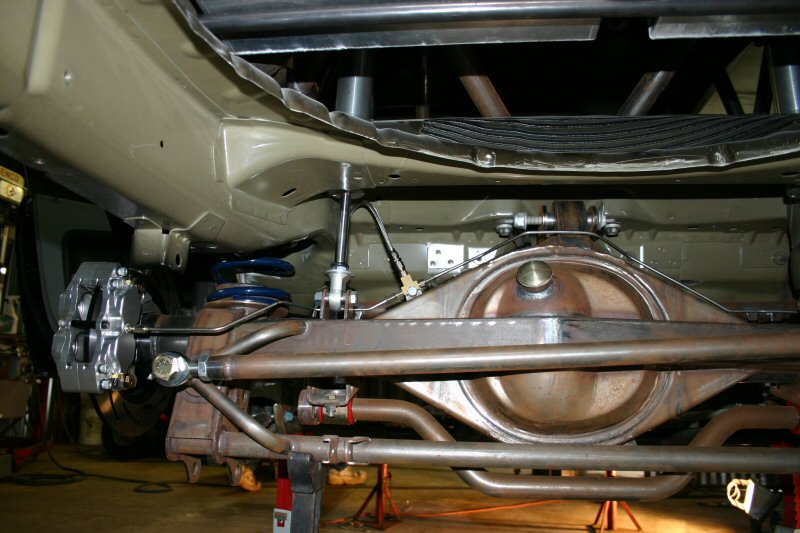 |
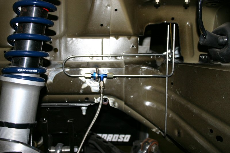
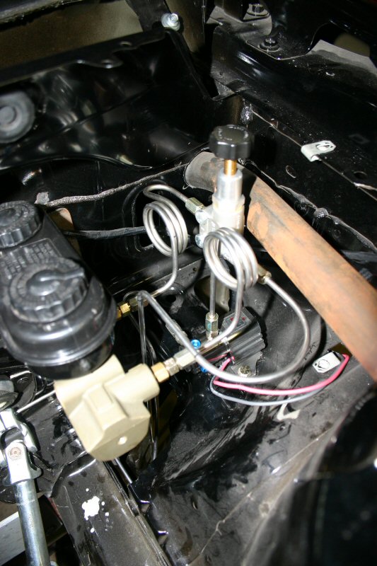
| While we were waiting on some parts to show up, we went ahead and plumbed the brake lines. All lines were made from 3/16" stainless hardline and #3 Teflon braided hose. A Hurst line lock and Strange proportioning valve were positioned to the right of the master cylinder. The brake line connecting from the drivers side to the passenger side was relocated to the firewall to allow the K-member to be removed without disconnecting the brake lines. |
May 6th, 2005
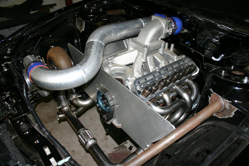
Just as the car seemed to be making progress, we lost an employee to medical leave for a month and the racing season kicked in. With no extra time to dedicate to the car, it was put on hold while we made every effort to keep business operating smoothly through this transition. Now that things are back to normal, our first project was the headers, y-pipe, and wastegate mounting.
 |
 |
 |
|
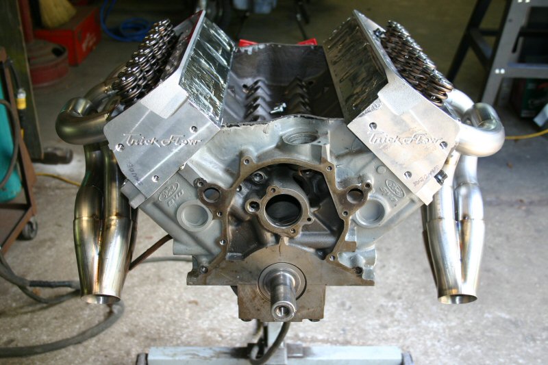
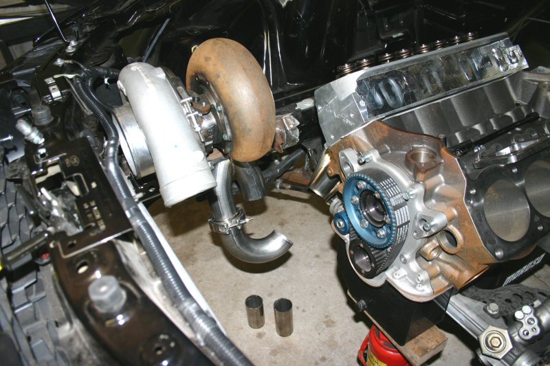
Measurements were taken while the engine was still in the car and the collectors were positiioned using one primary header tube to hold everything in place. At that point the engine was pulled and placed on an engine stand to fab the rest of the headers. Building headers on a stand is much more enjoyable than in the car. On the stand, it took approximately 4 hours to design and fit one side. With one side done, the other side only took 2 and a half hours to cut, fit and tack together. Before anything was final welded, the engine was put back into the car and everything was test fit one last time. Once everything was inspected for clearance, we started on the y-pipe. A custom 2 into 1 transition was fabricated that would bolt directly to our turbo and provide a common connection for each bank of cylinders. |
May 18th, 2005
 |
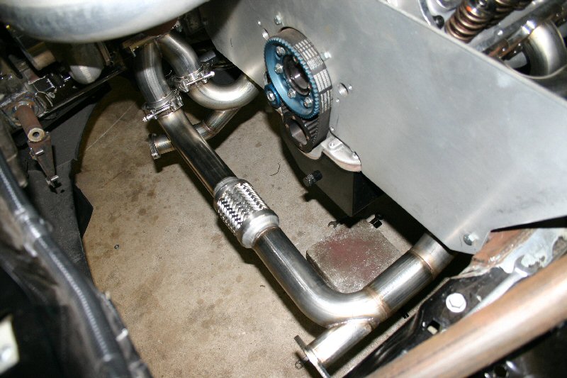 |
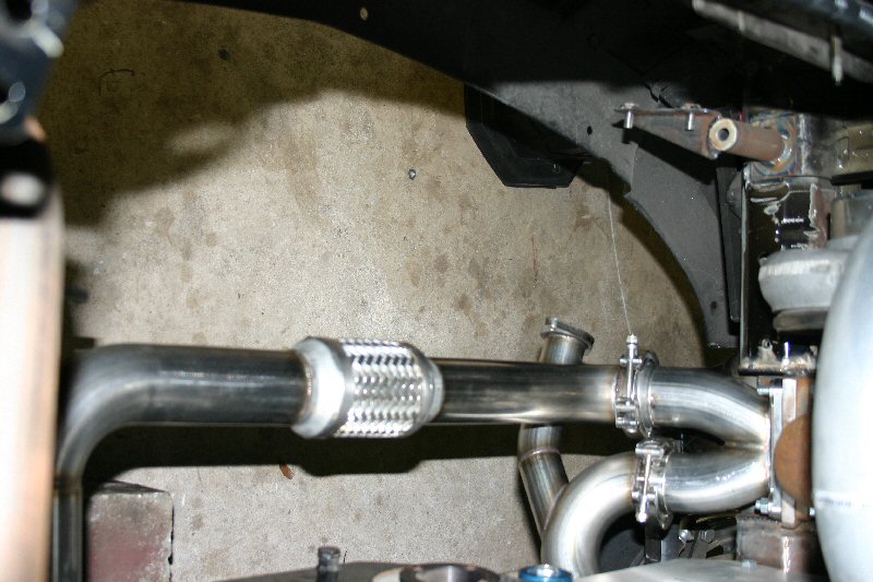
| V-band connections were used at each joint of the y-pipe and we incorporated a flexible union between the two sides. This prevents cracks that can form due to expansion and movement. The flanges facing forward are where the wastegates will mount. |
May 24th, 2005
 |
With the inlet side of the turbo taken care of, we decided to focus on the discharge side. With the manifold installed, the firewall was marked for cutting. A 3.5" hole saw was used to get a rough cutout and then it was final trimmed with an air saw and die grinder. Once a 4.125" hole was achieved through both layers of the firewall, we fabricated the passthrough tubes from 4" steel mandrel elbows. Both tubes have retention brackets attaching them to the firewall while still allowing easy removal. Once all the fabrication is done, these will be sent out to be ceramic coated inside and out, then siliconed into place to seal the cowl. |
 |
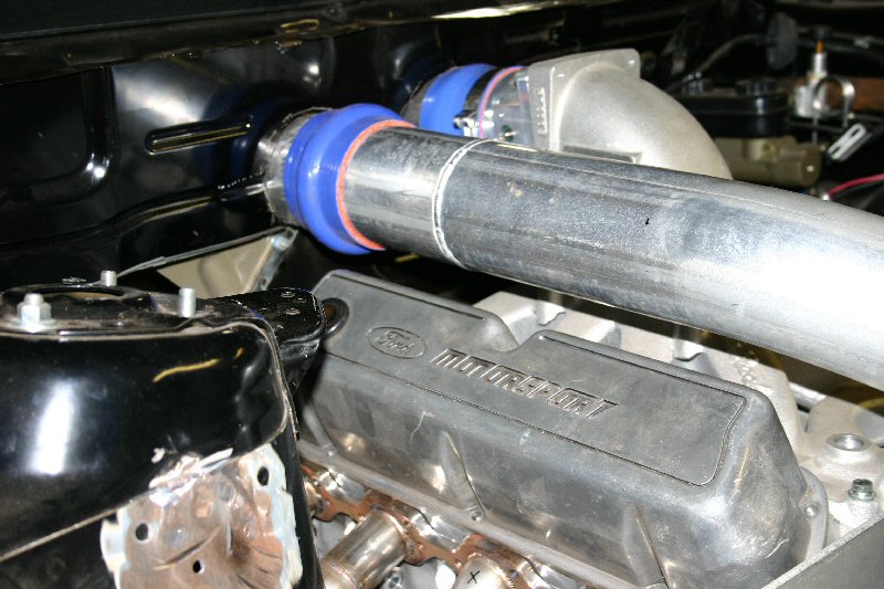 |
With the passthrough tubes in place, we then fabricated the main intake tube from the turbo to the firewall. A blowoff valve will also be attached to this tube at a later time when more of the accessories are in place. |
 |
May 31st, 2005
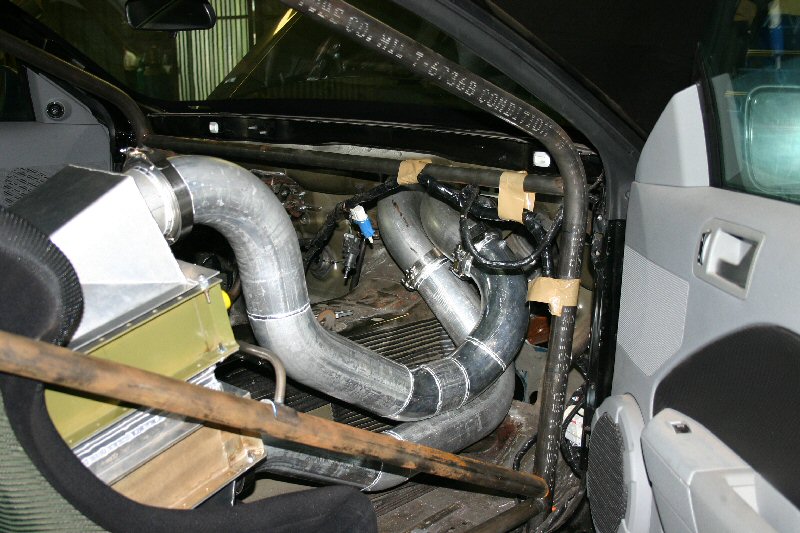
| The intercooler is too large to fit under the dashboard so we made a mount and positioned it in the passenger seat. Once mounted, all the tubing was fabricated, connecting it to the firewall passthrough tubes. All connections use O-ring seal V-band clamps. |
 |
 |
 |
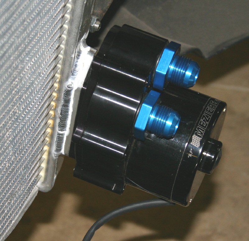
Since we were still setup for working with aluminum, we decided to install our cool new Meziere radiator mount water pump. This pump comes with a weld-on flange that attaches to the suction side of the radiator. You basically just cut off the lower hose bung, weld the flange in place and bolt on your water pump. Clean! |