BMR 7 Second Mustang Buildup
PAGE 2
January 10th, 2005 update - CHASSIS
|
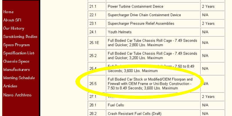
Chassis and rollcage construction requires a lot of planning before anything can be done. Interior layout, driver position, suspension mounts, and various other factors dictate bar positioning on the roll cage and chassis. Each car is different not only in physical interior dimensions but also in critical suspension points and structural frame rail locations. All sanctioning bodies mandate SFI build specifications for safety and reliability. The rules are continually being updated since the cars just keep getting faster. Because this car could eventually see 7.50's, the SFI Foundation was contacted and we ordered a set of their 25.5 spec sheets. SFI spec 25.5 is for use in a Full Bodied Car using the OEM Floorpan and Firewall with the OEM Frame or Uni-Body Construction – 7.50 to 8.49 Seconds; 3,600 lbs. Maximum. |
 |
|
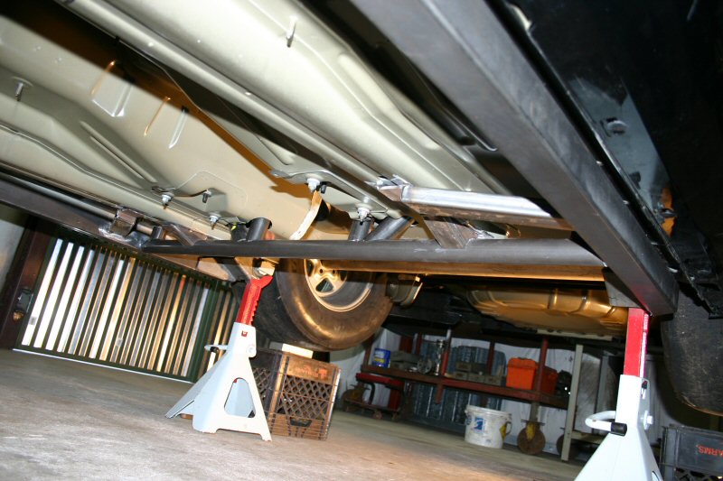
With the car leveled on stands, we are now ready to
begin work on the base chassis reinforcements and roll cage. The main
fabricators doing all of the roll cage work are Danny Adams and Kirt
Sanders. Danny is a well known chassis fabricator from this area who
is called in from time to time on special projects. He has earned a
respect for his meticulous precision and well thought out designs. Kirt
runs his own fab shop full time and welds for BMR on the side. He can
lay a TIG weld that rivals the best. With both of them working together
on this project, it's guaranteed to be a success.
|
 |
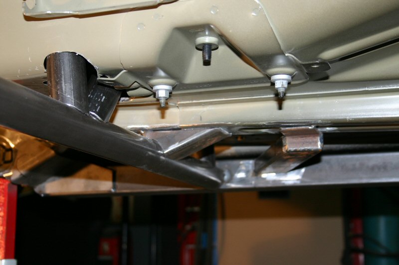 |
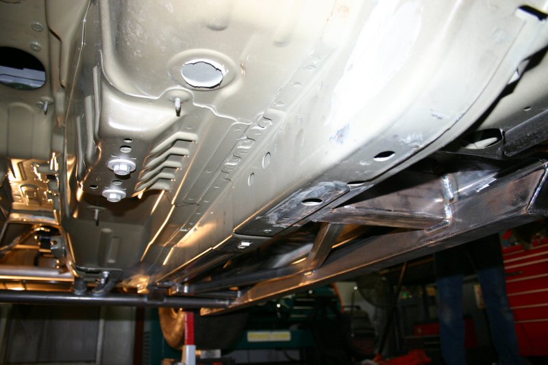
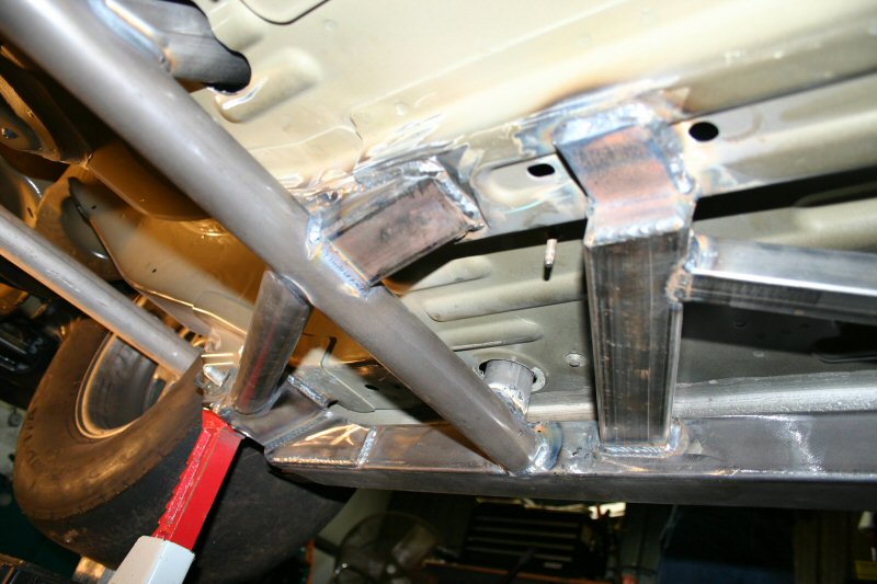
A modified set of BMR boxed subframe connectors are mocked up on the car so we can begin planning the roll cage design. Once in position, a rear crossmember was made from chromoly and tacked into place near the rear of the subframe connectors. This bar is important since it becomes a common link for the main hoop and lower vertical cage supports. It also ties the inner and outer frame rails together at a point directly in front of the control arm mounting points. |
| The next step is the main hoop. Main hoop dimensions are very critical in cage layout as it is the foundation of the roll cage. Shape and positioning dictate every other bar location in the cage design so it is critical that every aspect is considered before making it permanent. The main hoop was designed to conform to the interior lines as tight as possible while still allowing interior panel removal and providing weld accessibility for the rest of the connecting bars. Once every aspect was taken into consideration, the hoop was dimensioned and bent from chromoly and positioned in the car. |
| The rear seat footwells have two drain holes from the factory. Once removed they provided the perfect pass though for the main hoop to tie into the subframe connectors under the car. Thanks again Ford! |  |
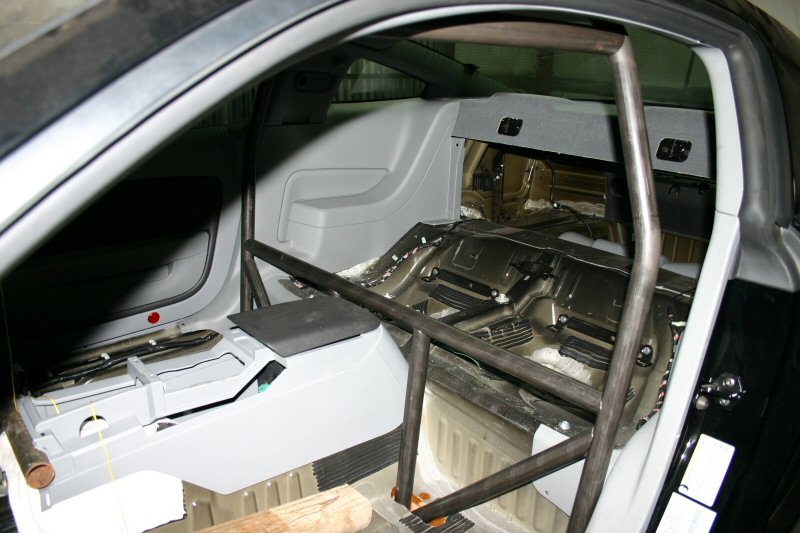 |
With the hoop positioned and tacked into place, the hoop crossbar and lower vertical cage supports were fabricated and positioned as well as the diagonal hoop supports. All three bars pass through the floor and connect to the rear crossmember. Since 25.5 specs require the use of a funny car cage around the driver, the hoop crossbar is positioned low. Once the seat is positioned, the funny car cage will attach to this bar. |
|
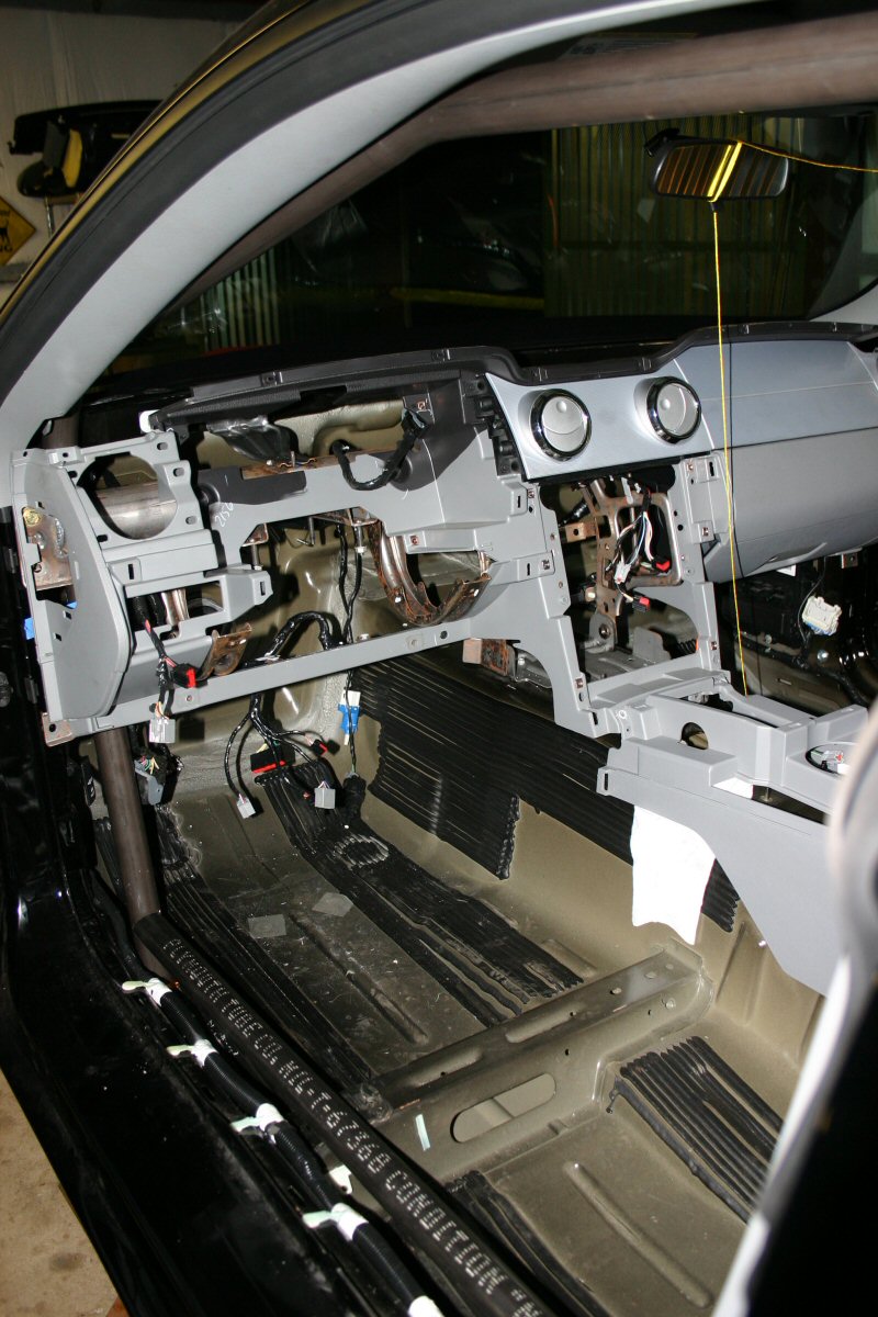
Since we plan on keeping all of the interior, it must continually be installed and removed to verify fitment. The dash has already been in and out of this car 20 times or more. Again, Ford made it easy on us by making the dash an assembly held in place with only 4 bolts. |
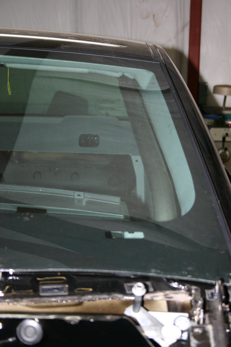 |
Fabricating A-pillar bars has always been one of the most difficult bars to make since they are bent on multiple plains. Generally it is necessary to remove the windshield in order to design, fit and install the A-pillar bar but since the entire dash comes out as an assembly, it was not necessary with this car. This turned out to be a blessing in disguise since it was later found out that it is almost impossible to remove this windshield without breaking it and a new windshield costs $750, ouch! Once the A-pillar bars were fabricated, they were positioned through the floor pan and tacked to the front of the subframe connectors. |
 |
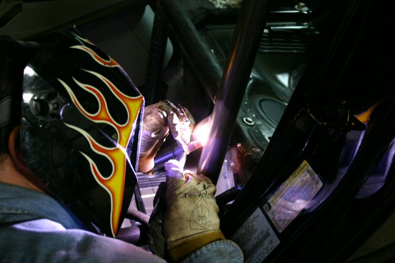
January 12th, 2005 update - ROLLCAGE
This update just shows more of the cage progress. The main hoop, rear crossmember, and A-pillar bars were welded permanently since the last update. Additionally, tubular reinforcement supports were welded onto the lower control arm mounts to stabilize the mount during launch.
 |
 |
 |
 |
 |
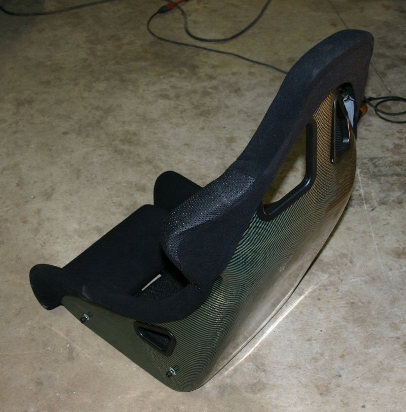
| We purchased some carbon fiber padded racing seats since the next step is positioning the driver. Once the seat is mounted, the funny car cage can be built. These seats weigh only 12lbs. each and are actually comfortable! |
 |
 |
January 24th, 2005 update - ROLLCAGE
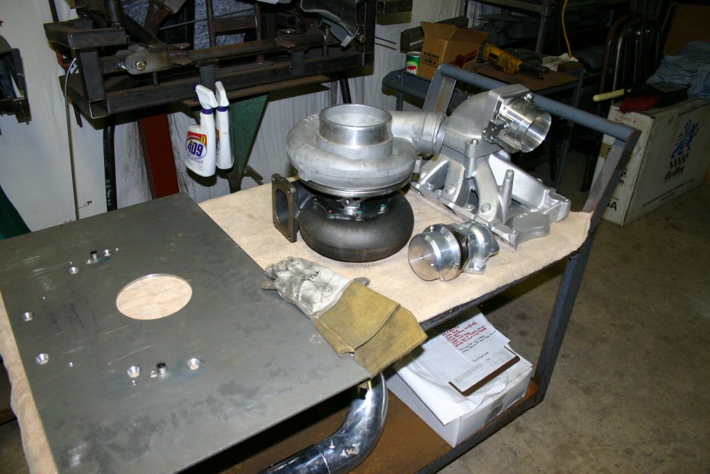 |
While the cage has been under construction, we have slowly started accumulating parts. The Edelbrock Super Victor manifold, Wilson elbow, and throttlebody, and Innovative turbo and wastegate are needed this early to begin mocking up the headers and turbo plumbing. Once the pinion centerline is established, the motor plates can be fabricated to position the motor properly. At that point, all of the headers, turbo mount, and intake plumbing can be mocked up. |
| Back to the cage..............Once the seats were positioned, the funny car cage could be fabricated around the driver. A few more bars and some final welding and this jungle gym will be done. |
 |
 |
 |
 |
 |
|
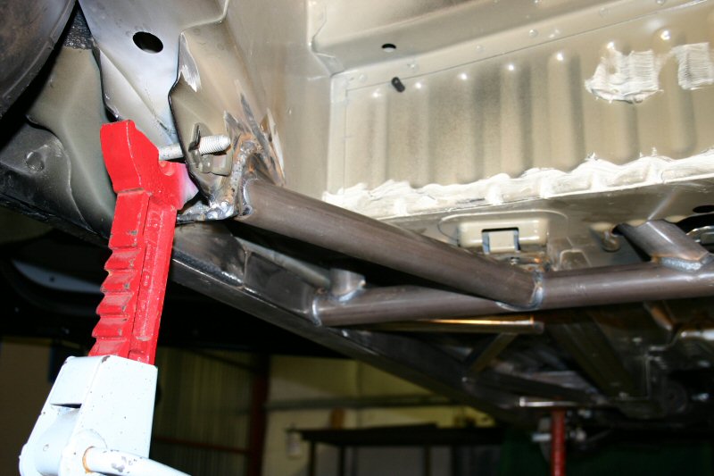
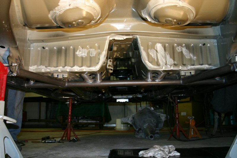
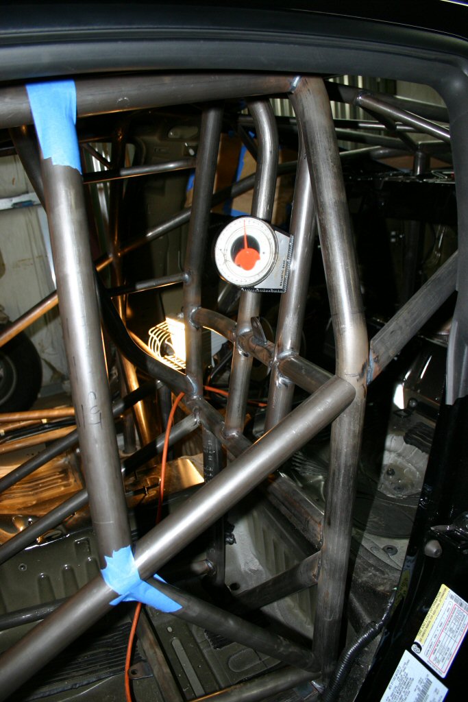
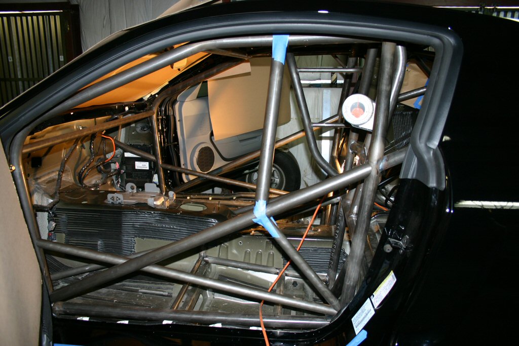
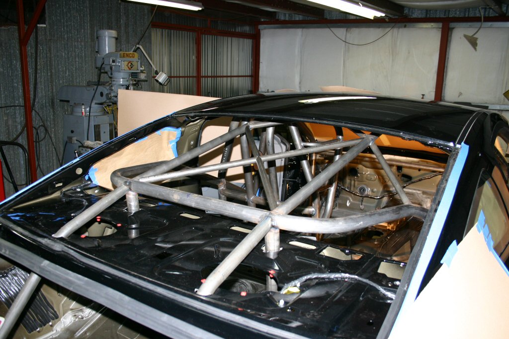
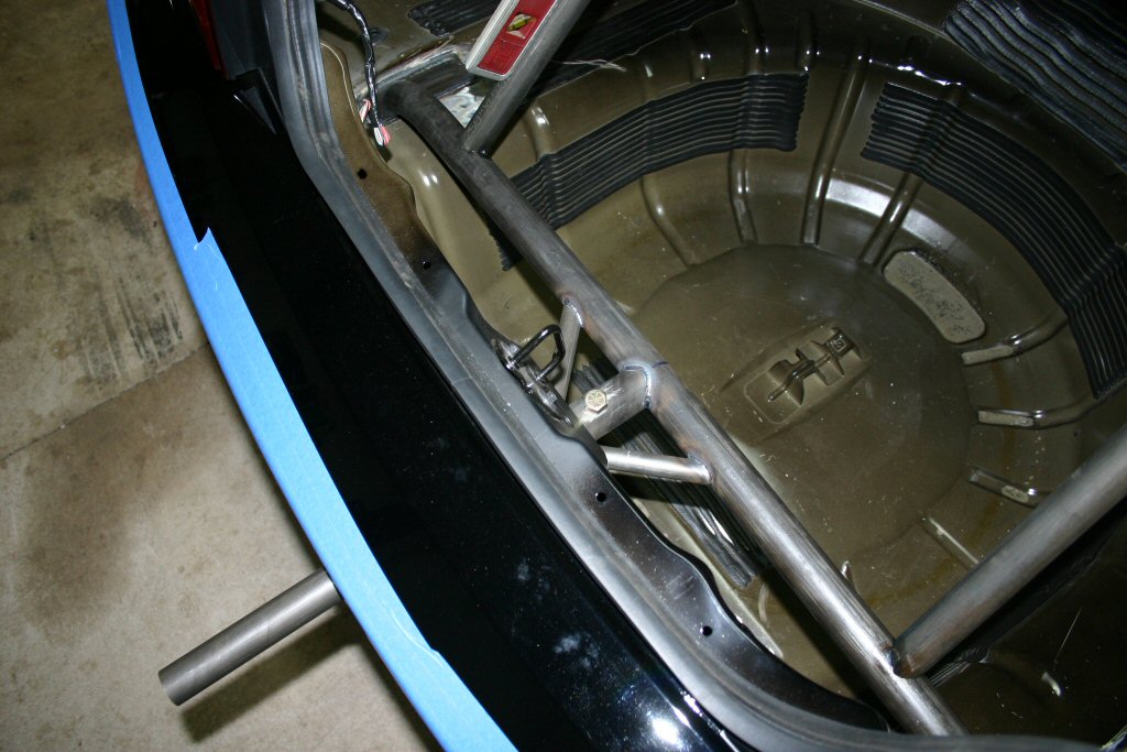
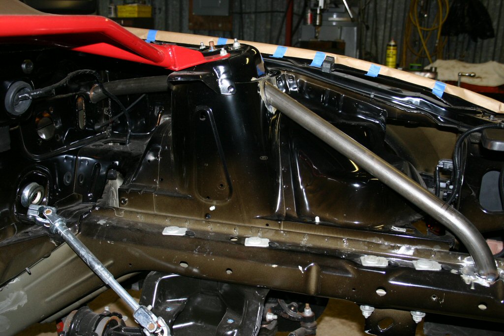
In the above images you can see the final stages of the rollcage. The first photo shows the rear hoop and x-brace. The down bars go through the package tray down to the trunk floor directly above the upper control arm mount. The rear bars off of the hoop also go down through the package tray and support the parachute mount shown in the second image. The parachute mount extends behind the license plate and can be removed by simply pulling a pin. The third image shows the engine bay bars that tie the strut towers to the rollcage. This was a very complicated tube that goes through the firewall and welds to the front A-pillar bars close to the x-brace. At this point the cage is primarily complete. We still have a few tabs, gussetts and some small bars to add but the focus now will turn to the rearend setup, shock mounts and wheelwell modifications. |
February 4th, 2005 Update - REAREND
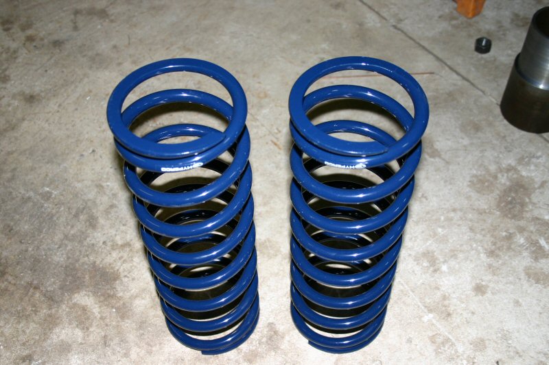 |
With our goal weight for the car at 3000 lbs. and an estimated front/back weight ratio of 60/40 each rear spring will need to support roughly 600 lbs. We knew that we wanted to use the longest spring possible so we chose a 15" x 5.5" Hyperco spring. Using a compressed height of 11 inches, the rate calculator told us we needed a 150 lb/in spring so that is where we will start. Once the car is finished and scaled, it may be necessary to change the rates. |
 |
|
Since the new springs were taller by about 3 inches and the car needed to sit as low as possible, it was necessary to deepen the spring cups in the frame. The top of the original cups were cut out and a set of extensions were fabricated from 6" round tubing. While we were at it, a set of spring jacks were fabricated to allow ride height adjustability. The aluminum spring seats shown in the image above right attach to the threaded jack bolts shown in the image to the right. The springs seat on these jacks and the ride height can be adjusted by simply turning the jack bolt with a 3/8" ratchet. You can also see in this image that the inner wheelwell has been removed. In order to get a big drag radial in the wheelwell, the inner wheeltubs are being moved inward 2 inches and will butt up against the new spring cups. |
 |
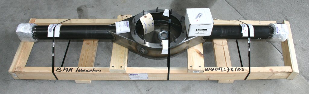 |
Since nobody makes a bolt-in Ford 9" housing for the '05 Mustang yet, a bare Strange 9" housing was ordered in. It will be necessary to fabricate the control arm, panhard rod, spring, and shock mounts on this rear and since we do not yet know the exact overall width, the rear was ordered 60" wide without the housing ends installed. Once mocked up in the car, we will determine the proper width and narrow it accordingly. |